


Looking up parts for your B1550E? This 269-page Kubota Parts Catalog lays out exploded views and OEM numbers exactly the way the factory built the tractor. Engine coverage runs 60 pages across the crankcase, pistons, injection pump, and governor. Drivetrain breakdowns take another 30 pages from clutch through rear differential. Chassis work (front axle, steering, wheels, brakes) fills 50 pages, and hydraulic assemblies including the lift arm, control valve, and gear pump take 20 more. Nozzle adjusting washer? 1.00 mm. Hydraulic gear pump runs a 27T gear. Fuse rating is 15A. Stop ordering wrong parts off blurry forum photos. Bookmarked by system and searchable by part number, so you pull it up on your phone at the parts counter and order right the first time.
What's Inside This Kubota B1550E Parts Manual
| System | Pages |
|---|---|
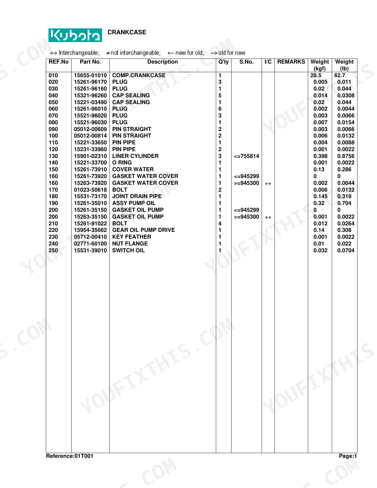
| Crankcase | 6-7 |
| Oil Pan | 8-10 |
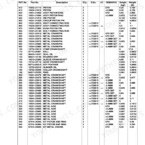
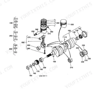
| Piston/Crankshaft | 11-12 |
| Main Bearing Case | 13-14 |
| Flywheel | 15-17 |
| Cylinder Head | 18-19 |
| Valve/Rocker Arm | 20-21 |
| Nozzle Holder | 22-23 |
| Nozzle Holder [Component Parts] | 24-25 |
| Cylinder Head Cover | 26-28 |
| Inlet Manifold | 29-30 |
| Exhaust Manifold | 31-32 |
| Camshaft | 33-34 |
| Gear Case | 35-36 |
| Water Pump | 37-38 |
| Tension Pulley [Ca] | 39-40 |
| Water Flange | 41-42 |
| Fuel Pump | 43-44 |
| Injection Pump | 45-46 |
| Injection Pump [Component Parts] | 47-48 |
| Engine Stop Lever | 49-50 |
| Speed Control Plate | 51-52 |
| Governor | 53-54 |
| Upper Gasket Kit | 55-56 |
| Lower Gasket Kit | 57-58 |
| Dynamo [A Au] | 59-60 |
| Alternator [Ca] | 61-62 |
| Dynamo [A Au] [Component Parts] | 63-64 |
| Alternator [Ca] [Component Parts] | 65-66 |
| Clutch | 67-68 |
| Hydraulic Gear Pump | 69-70 |
| Hydraulic Gear Pump [Component Parts] | 71-73 |
| Air Cleaner | 74-75 |
| Muffler | 76-77 |
| Horizontal Muffler [Option] | 78-79 |
| Engine Stop Rod | 80-82 |
| Accelerator Lever | 83-84 |
| Fuel Tank | 85-86 |
| Fuel Pipe | 87-88 |
| Fuel Filter [Component Parts] | 89-90 |
| Water Pipe | 91-93 |
| Radiator | 94-96 |
| Starter | 97-98 |
| Starter [Component Parts] | 99-100 |
| Battery | 101-103 |
| Light | 104-106 |
| Working Light [Option] | 107-108 |
| Panel / Switch [A Au] | 109-111 |
| Panel Board [Component Parts] | 112-113 |
| Wire Harness [A Au] | 114-115 |
| Clutch Rod | 116-117 |
| Clutch Pedal | 118-119 |
| Clutch Housing | 120-121 |
| Transmission Case | 122-124 |
| Transmission Case Cover | 125-126 |
| Propeller Shaft | 127-128 |
| 1St Shaft | 129-131 |
| 2Nd Shaft | 132-133 |
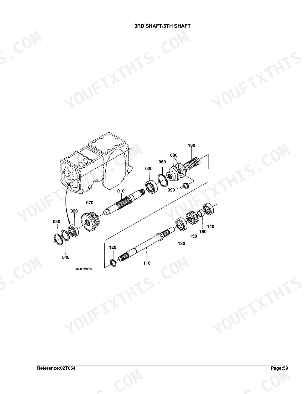
| 3Rd Shaft/5Th Shaft | 134-135 |
| 4Th Shaft | 136-137 |
| Pinion Shaft Gear | 138-139 |
| Reverse Shaft | 140-142 |
| Rear PTO | 143-145 |
| Mid PTO | 146-147 |
| Front PTO [Option] | 148-149 |
| Main Gear Shift Lever | 150-151 |
| Main Gear Shift Fork | 152-153 |
| Range Gear Shift Lever | 154-155 |
| PTO Gear Shift Lever | 156-157 |
| Rear Differential | 158-159 |
| Diff.Lock Pedal | 160-161 |
| Rear Axle | 162-163 |
| Rear Axle Case | 164-165 |
| Rear Wheel (7-16) | 166-168 |
| Rear Wheel (8-16) | 169-171 |
| Rear Wheel (29 X 12.00-15) | 172-174 |
| Rear Wheel (31 X 13.5-15 Bar) [A] | 175-177 |
| Brake | 178-179 |
| Brake Rod | 180-181 |
| Brake Pedal | 182-183 |
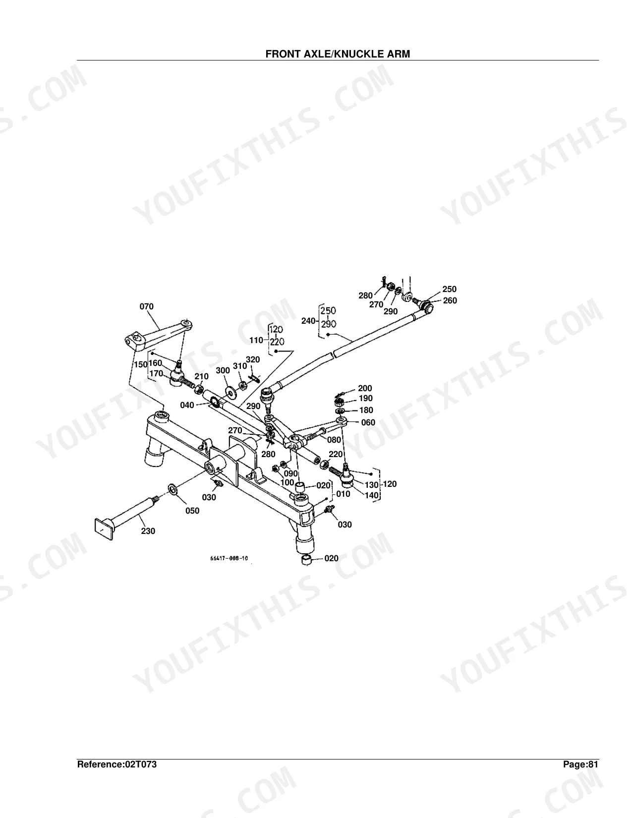
| Front Axle/Knuckle Arm | 184-185 |
| Front Wheel Hub | 186-187 |
| Front Wheel (4.50-10) | 188-189 |
| Front Wheel (5.00-10) | 190-191 |
| Front Wheel (18 X 9.50-8) | 192-193 |
| Front Drive Lever | 194-195 |
| Front Axel Frame | 196-198 |
| Manual Steering | 199-201 |
| Power Steering | 202-203 |
| Manual Steering [Component Parts] | 204-205 |
| Power Steering [Component Parts] | 206-207 |
| Hydraulic Pipe (Ps) | 208-209 |
| Hydraulic Pipe (Front) | 210-211 |
| Hydraulic Pipe (Rear) | 212-213 |
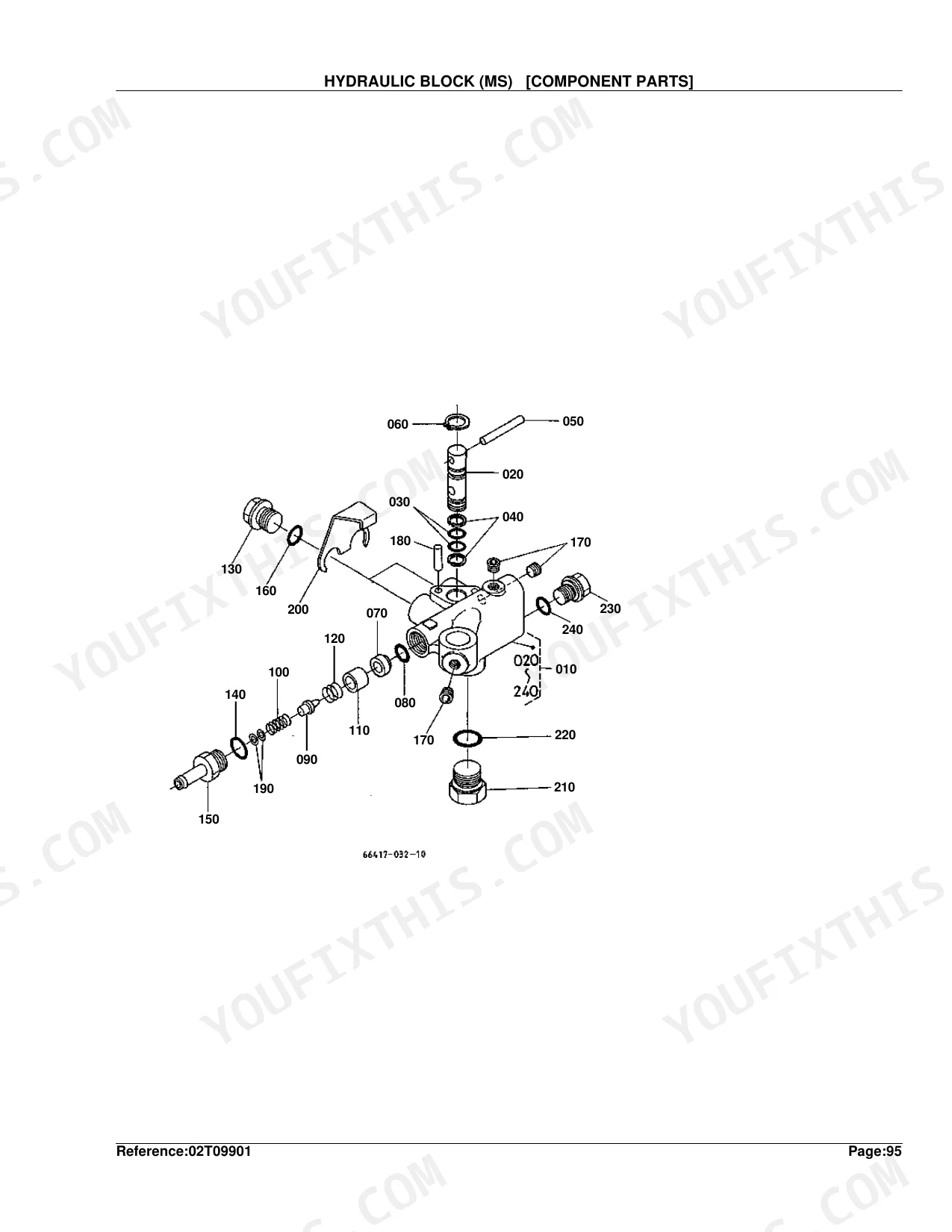
| Hydraulic Block (Ms) [Component Parts] | 214-215 |
| Hydraulic Block (Ps) [Component Parts] | 216-217 |
| Lift Arm | 218-220 |
| Hyd.Cylinder Cap [Component Parts] | 221-226 |
| Control Valve | 227-228 |
| Control Valve [Component Parts] | 229-231 |
| Top Link | 232-233 |
| Lower Link | 234-235 |
| Lifting Rod | 236-237 |
| Hood (Bonnet) | 238-239 |
| Lace | 240-241 |
| Hood Cover Rear | 242-243 |
| Skirt (Front) | 244-245 |
| Skirt (Side) | 246-248 |
| Dust Cover | 249-250 |
| Tank Support | 251-252 |
| Fender | 253-255 |
| Seat | 256-257 |
| Step | 258-259 |
| ROPS [A Ca] | 260-263 |
| Label 1 | 264-265 |
| Label 2 | 266-268 |
| Accessories and Service Parts | 269-269 |
Quick Reference Specifications
| Specification | Value | Page |
|---|---|---|
| Nozzle Adjusting Washer Thickness | 1.00MM | p. 25 |
| Injection Pump Shim Thickness | 0.20MM | p. 46 |
| Hydraulic Gear Pump, Gear Tooth Count | 27T | p. 70 |
| Fuse Rating | 15A | p. 115 |
| 2nd Shaft Gear Tooth Count | 29T | p. 133 |
| 3rd Shaft/5th Shaft Shim Thickness | 0.5MM | p. 135 |
| Pinion Shaft Gear Shim Thickness | 1.4MM | p. 139 |
| Rear PTO Gear Tooth Count | 22T | p. 145 |
| Rear Differential Bevel Gear Assembly Ratio | 6-37T | p. 159 |
| Rear Axle Gear Tooth Count | 55T | p. 163 |
| Front Wheel Hub Shim A Thickness | 1.0MM | p. 187 |
| Manual Steering Shim Thickness | 0.05MM | p. 205 |
Kubota B1550E Common Problems This Manual Covers
Kubota B1550E fuel filter element part number lookup for hard starting after long storage p. 89
Open the Fuel Filter Component Parts exploded view on page 89. Match the filter body casting number to the diagram callouts, then pull the element and bowl O-ring part numbers from the parts list. Cross-reference against your serial number range before ordering. Confirm the 15A fuse rating on page 115 matches your panel before reassembly.
Manual Section: Fuel Filter [Component Parts]Need correct hydraulic gear pump rebuild kit part numbers for weak 3-point hitch lift p. 71
Pull up the Hydraulic Gear Pump Component Parts breakdown on page 71. Confirm your pump is the 27T gear tooth count version listed on page 70 before ordering. Identify the body gasket, shaft seal, and gear set part numbers from the exploded view callouts. Check the control valve component parts on page 229 if internal leakage is suspected.
Manual Section: Hydraulic Gear Pump [Component Parts]Radiator and water pump replacement part numbers for overheating during mowing p. 94
Reference the Radiator exploded view on page 94 to identify the core, cap, and lower hose part numbers. For coolant flow components, cross to the Water Pump diagram on page 37 and the Water Pipe assembly on page 91. Match your tension pulley callout against page 39 before ordering the fan belt. Tie all numbers to your serial range.
Manual Section: RadiatorCan't identify PTO clutch and rear PTO gear part numbers for slipping engagement p. 67
Start on the Clutch exploded view on page 67 for clutch disc, pressure plate, and release bearing callouts. Then go to the Rear PTO parts diagram on page 143 and verify your unit uses the 22T gear listed on page 145. Pull part numbers from the parts list adjacent to each diagram. Confirm linkage components against the PTO Gear Shift Lever view on page 156.
Manual Section: ClutchWheel seal and axle gasket part numbers needed for rear axle oil leak p. 162
Locate the outer wheel seal and axle shaft O-ring callouts on the Rear Axle diagram, page 162. Cross-reference with the Rear Axle Case exploded view on page 164 for inner seals and case gaskets. Confirm your unit matches the 55T axle gear count on page 163 before ordering. Pull all part numbers from the adjacent parts list, matched to serial range.
Manual Section: Rear AxleStarter solenoid and battery cable part number identification for no-crank condition p. 99
Grab the Starter Component Parts exploded view on page 99 for solenoid, brush set, and drive pinion callouts. Cross to the Battery diagram on page 101 for cable, terminal, and hold-down part numbers. Check the Wire Harness routing on page 114 and confirm the 15A fuse rating on page 115 before ordering replacements. Match all part numbers against your serial number range.
Manual Section: Starter [Component Parts]Frequently Asked Questions
What are the replacement specifications for fuel filter?
Fuel filter assembly is part number 15751-43010. The filter element itself is listed as ASSY ELEMENT, part number 15231-43560. Both are in the FUEL FILTER [COMPONENT PARTS] section.
What are the replacement specifications for engine oil filter?
Engine oil filter is part number 15531-32110, listed at reference number 060 in the OIL PAN section of the parts manual.
What format is this Kubota B1550E manual in?
Instant download of the full 269-page searchable Parts Catalog. Open it on any device, laptop at your desk or phone in the field.
Is this Kubota B1550E Parts Catalog printable?
No restrictions. Print single pages, full chapters, or the whole manual. The PDF is fully unlocked.
Are there hydraulic schematics in this Kubota B1550E manual?
Detailed exploded diagrams cover all hydraulic components, including the gear pump, control valve, and lift cylinder. It does not contain hydraulic schematics, flow diagrams, or pressure specifications.
Document Quality
This is a scanned parts manual that has been processed with OCR, allowing you to search the full text and copy part numbers directly. The text in the parts lists is clear and legible, while the diagrams are raster images that show some pixelation when zoomed in. Most reference numbers on the illustrations are readable, though a few can be slightly blurry. The pages are generally clean, with only minor scan artifacts and a slight skew on some pages that does not obstruct the content.


Reviews
There are no reviews yet.