
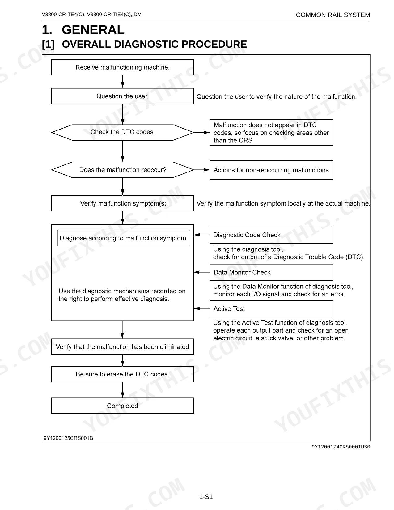


Chasing a fault code through a generic service manual wastes the afternoon. This 335-page Kubota diagnostic volume (OEM #9Y120-01740) gives the common rail system its own dedicated path. It carries wiring diagrams for the engine intermediate, injector, and ECU harnesses, plus ECU terminal layouts for engine-side and machine-side connectors, so you probe the right pins the first time. The DTC section runs 174 pages, P0016 through U0089, each code cross-referenced by SPN/FMI, alongside a symptom track for hard no-starts, idle failure, excessive smoke, and poor acceleration. Confirm idle at 800 min-1 and boost near 100 kPa before blaming rail pressure. Coverage spans all four variants: V3800-CR-TE4, V3800-CR-TIE4, V3800-CR-TE4C, and V3800-CR-TIE4C. Bookmarked by section, searchable by DTC on your laptop.
What's Inside This Kubota V3800 Series Manual
| System | Pages | Key Topics |
|---|---|---|
| Information | - | Contents (Safety First), Safety First, Before Servicing and Repairing, Safety Starting, Safety Working, Avoid Fires, Ventilate Work Area, Prevent Acid Burns |
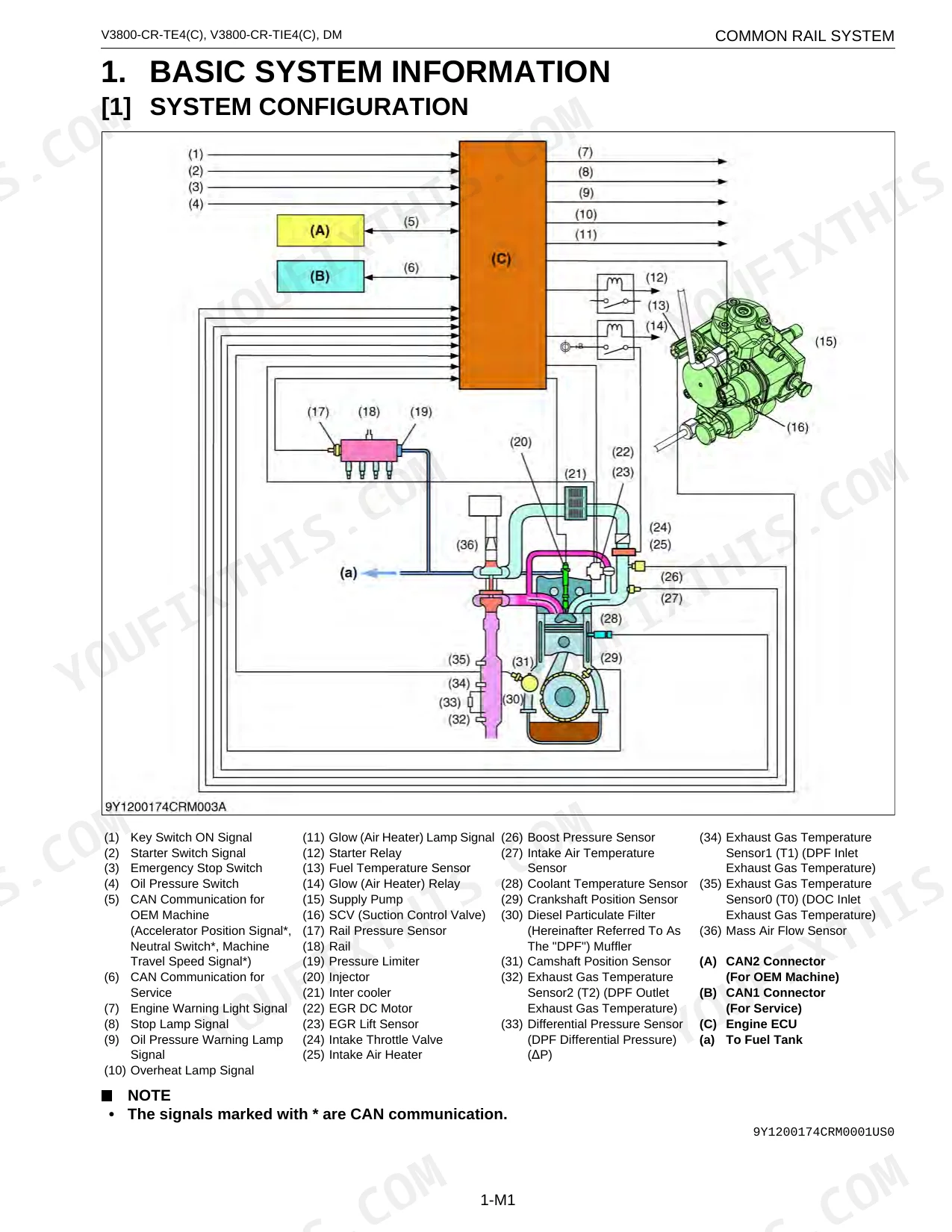
| Basic System Information | - | System Configuration, Fuel System Components, Intake and Exhaust System Components |
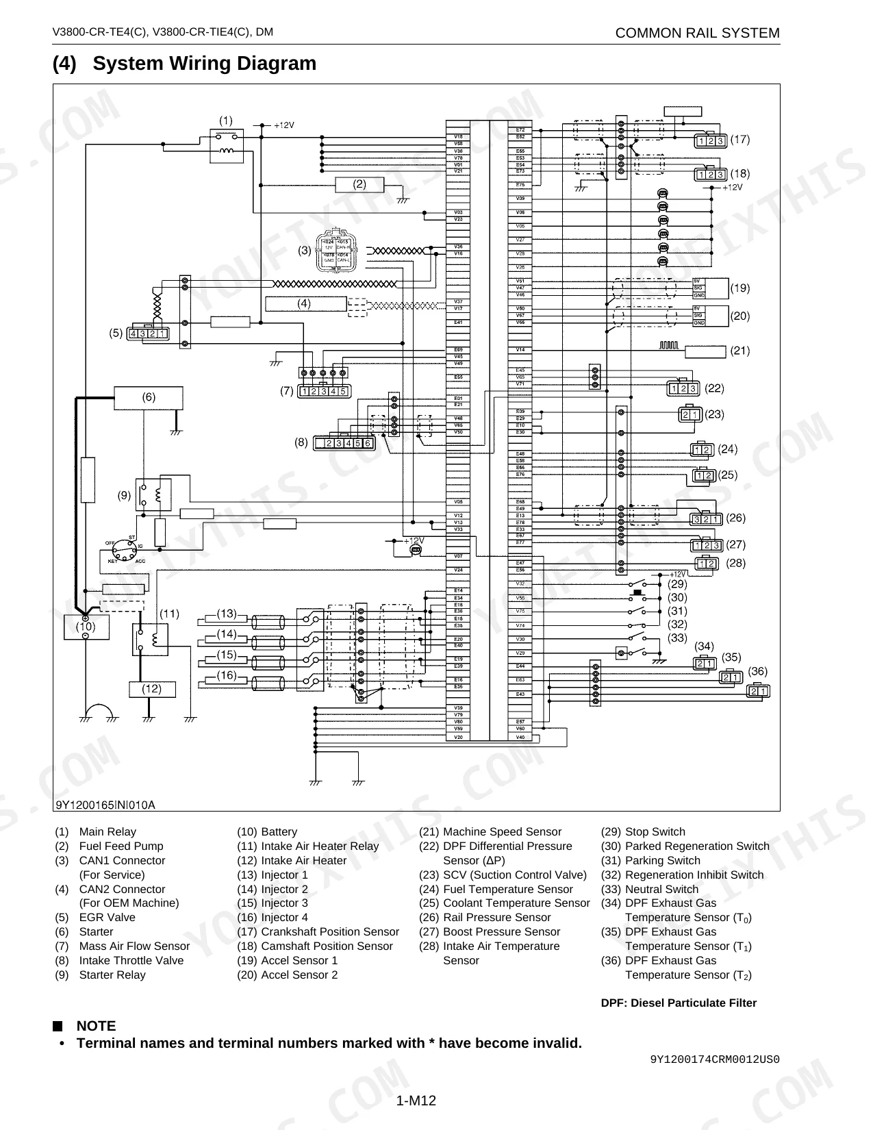
| Wiring Diagram | - | Engine Intermediate Harness, Injector Intermediate Harness, ECU Intermediate Harness, System Wiring Diagram |
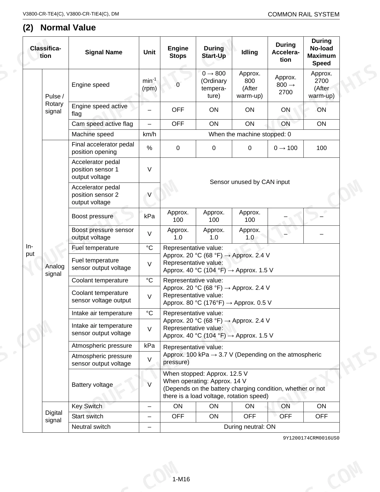
| Available Data Monitor Signals (Level 2) | - | Monitor Items, Normal Value, Pulse/Rotary Signal, Analog Signal, Digital Signal |
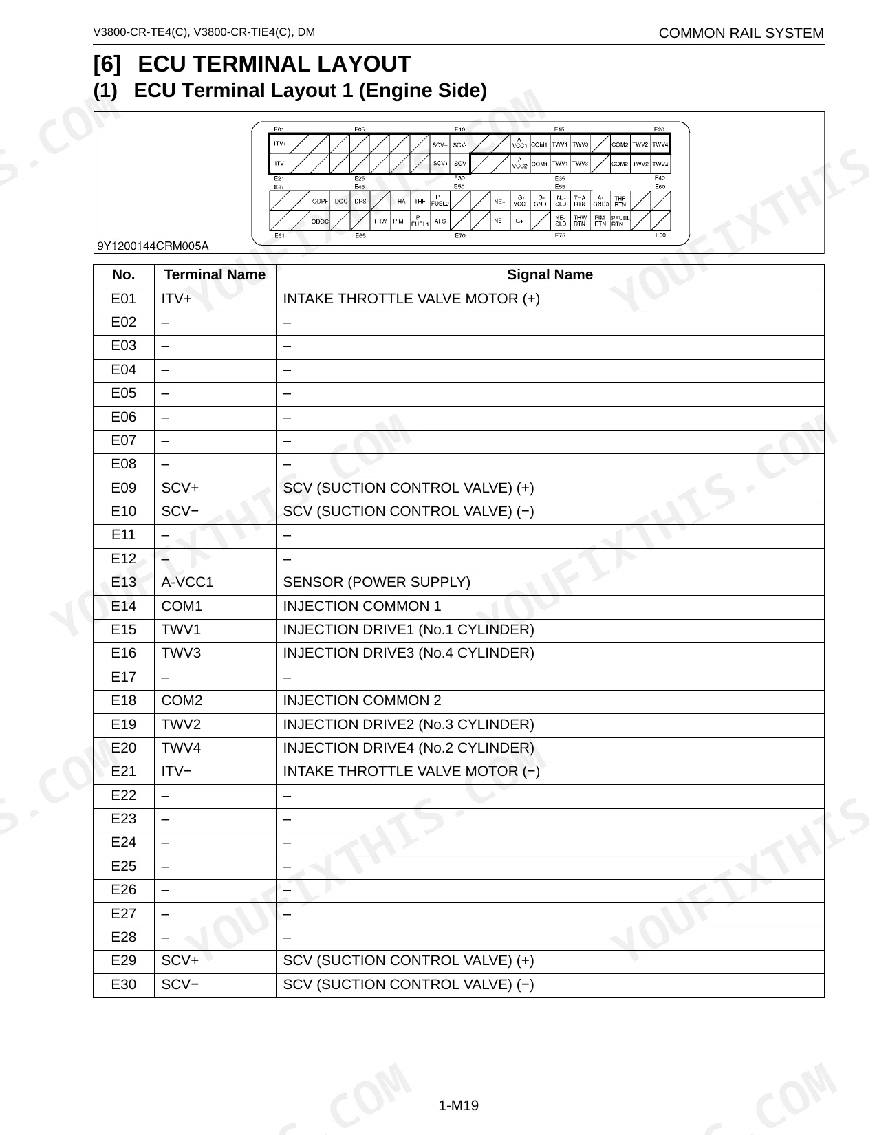
| ECU Terminal Layout | - | ECU Terminal Layout 1 (Engine Side), ECU Terminal Layout 2 (Machine Side) |
| Diagnostic Tool Connection Procedure | - | Diagnostic Connector Positions, Checking the Communication Operation of the Interface, Checking the Operation of the ECU, Starting Diagmaster, DST-i Communication Settings |
| Active Test and Supply Pump Difference Learning | - | Injector Non-Injection Instruction, EGR Actuation Test, Air Heater Relay Actuation Test, Supply Pump Difference Learning |
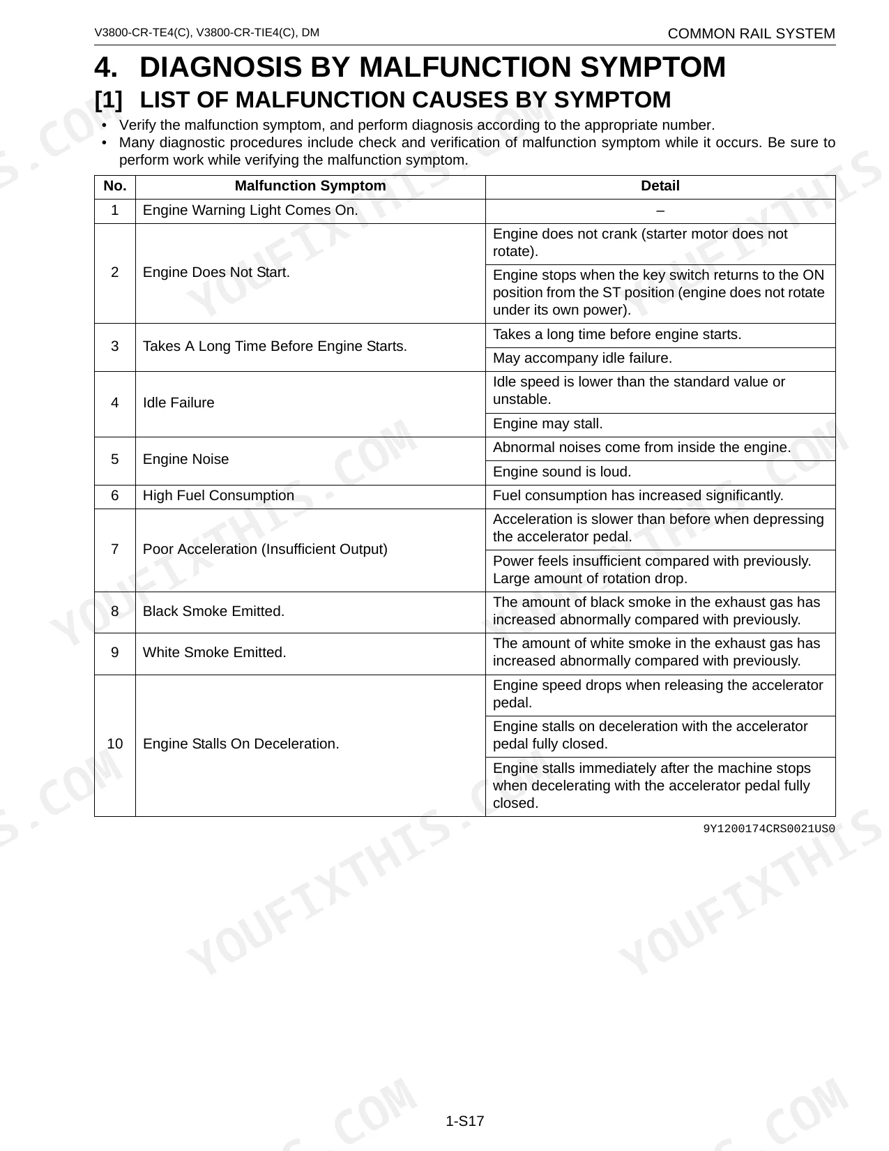
| Diagnosis by Malfunction Symptom | - | List of Malfunction Causes by Symptom, Engine Warning Light Comes On, Engine Does Not Start, Takes A Long Time Before Engine Starts, Idle Failure, Engine Noise |
| Diagnostic Procedure by Dtc | - | Dtc List, NE - G Phase Shift, Intake Air Temperature Built-in MAF Sensor: Abnormality, Pressure Limiter Emergency Open, High Rail Pressure, SCV Stuck, Fuel Leak |
| Inspection Procedure for Each System | - | Air Intake System Inspection Procedure, Fuel System Inspection Procedure, Electric System Inspection Procedure, Basics Of Checking Electrical / Electronic Circuit Systems |
Quick Reference Specifications
| Specification | Value | Page |
|---|---|---|
| Engine oil type | API Service Classification CF grade or higher | p. 40 |
| Fuel Cetane Rating (minimum) | 45 | p. 287 |
| Air cleaner element cleaning interval (Primary and Secondary) | Every 250 hours | p. 291 |
| Air cleaner element replacement interval | Once yearly or after every sixth cleaning, whichever comes first | p. 291 |
| Engine Speed (Idling) | 800 min-1 (rpm) | p. 24 |
| Engine Speed (No-load Maximum Speed) | 2700 min-1 (rpm) | p. 24 |
| Battery Voltage (Stopped) | 12.5 V | p. 24 |
| Battery Voltage (Operating) | 14 V | p. 24 |
| Target Rail Pressure (Idling) | 40 to 50 MPa | p. 25 |
| Target Rail Pressure (No-load Maximum Speed) | 95.0 to 115 MPa | p. 25 |
| Target Suction Control Valve (SCV) Current (Idling) | 1700 to 2000 mA | p. 25 |
| Intake Air Temperature Sensor Resistance (20 °C) | 2.43 kΩ | p. 150 |
Kubota V3800 Series Common Problems This Manual Covers
The V3800-CR-TE4 logs active DTC P0089, output drops, and the engine stops p. 234
Check the suction control valve circuit. Measure SCV resistance at 20 °C; it must be 2.1 Ω as detailed on page 234. Verify target rail pressure at idling is 40 to 50 MPa per page 25. Replace the SCV if resistance is out of specification.
Manual Section: SCV Stuck (DTC P0089 / 1347-7)Fault code DTC P0072 or P0073 appears with MAF sensor low voltage and open circuit p. 148
Inspect the intake air temperature sensor wiring for a short to ground. Measure sensor resistance at 20 °C; the reading should be 2.43 kΩ as shown on page 148. If it falls outside spec, replace the sensor and clear the codes.
Manual Section: Intake Air Temperature Built-in MAF Sensor Abnormality (DTC P0072 / 171-4, P0073 / 171-3)On the V3800-CR-TIE4, active DTC P0611 shows up intermittently with poor exhaust performance and the engine stops p. 193
Trace the injector intermediate harness for breaks or loose pins. Measure the injector terminal resistance and confirm against page 193 that it reads 0.35 to 0.55 Ω. If resistance runs high, clean the connector contacts and retest the circuit before replacing the injector.
Manual Section: Injector Charge Voltage Abnormality (DTC P0611 / 523525-1)Fault code DTC P0088 triggers alongside worsening exhaust gas performance and insufficient output p. 25
Test the fuel system to isolate the high-pressure fault. Monitor target rail pressure at idling; it should read roughly 40 to 50 MPa per page 25. Inspect the fuel lines for blockages and confirm the pressure limiter valve still operates correctly.
Manual Section: High Rail Pressure (DTC P0088 / 157-0)Frequently Asked Questions
What are the recommended service intervals?
Clean the air cleaner element (Primary and Secondary) every 250 hours, and replace it yearly or after the sixth cleaning, whichever comes first. Swap the fuel filter every 500 operation hours. On biodiesel, halve those intervals for the fuel filter cartridge, rubber piping, and clamp bands.
What fluids and capacities does this machine require?
Run diesel with a Cetane Rating of at least 45, ideally above 50 below –20 °C (–4 °F) or above 1500 m (5000 ft). In US EPA regulated areas, ultra low sulfur fuel (No.2-D S15 or No.1-D S15) is mandatory, with sulfur held under 0.0015% (15 ppm). Engine oil should be API Service Classification CF grade or higher.
How to troubleshoot engine won't start?
When the V3800-CR-TE4 won't start, turn the key switch ON and confirm the fuel pump runs. If it stays silent, go to page 1-S289 for the pump inspection procedure. Then connect a diagnosis tool, read any DTCs, and follow the matching guidelines. Likely causes: a fuel pump fault, the starting assist device (intake air heater) below -10 °C (14 °F), low compression, control system damage, or an electrical fault.
What are the hydraulic system specifications?
No hydraulic system specifications appear in this manual. The only hydraulic mention is a safety warning: relieve pressure before disconnecting lines, since escaping fluid under pressure can cause serious injury.
Is this Kubota V3800 Series Diagnostic Manual a digital download?
Checkout delivers a 335-page searchable PDF, downloadable right away. Open it on a laptop, tablet, or phone and carry it onto the shop floor.
Am I able to print pages from this Kubota V3800 Series manual?
Yes. The PDF carries no DRM, so you can print any page or section your shop needs on any standard printer.
Does this Kubota V3800 Series manual include wiring diagrams?
Yes. Full electrical schematics are included, with wire colors, connector locations, and circuit descriptions.
Document Quality
This document is a native digital PDF, allowing you to search and copy the full text content. The text is consistently crisp and easy to read throughout. Diagrams and illustrations, including wiring schematics and component layouts, are sharp with clearly readable labels. All pages are clean, free from scan artifacts, stains, or skewing, presenting a professional appearance. There are no notable blank or filler pages within the document.


Reviews
There are no reviews yet.