


Factory service data for the B26 tractor, TL500 front loader, and BT820 backhoe, OEM #9Y111-00042, across 448 bookmarked pages. Hydraulic teardown runs 50 pages; engine, transmission, rear axle, brakes, front axle, and steering procedures fill another 300. Wiring coverage, 15 pages of troubleshooting charts, 26 pages of service intervals, and exploded views for every major assembly round it out. Key numbers you will hit often: M16 main frame mounting bolts at 200 to 225 N·m, TL500 bucket cylinder head at 250 to 300 N·m, BT820 stabilizer cylinder head at 500 to 550 N·m, HST filter every 200 hours. Bookmarked by system, so you can open the right section on a tablet and walk straight to the shop with the answer.
What's Inside This Kubota B26, TL500, BT820 Manual
| System | Pages | Key Topics |
|---|---|---|
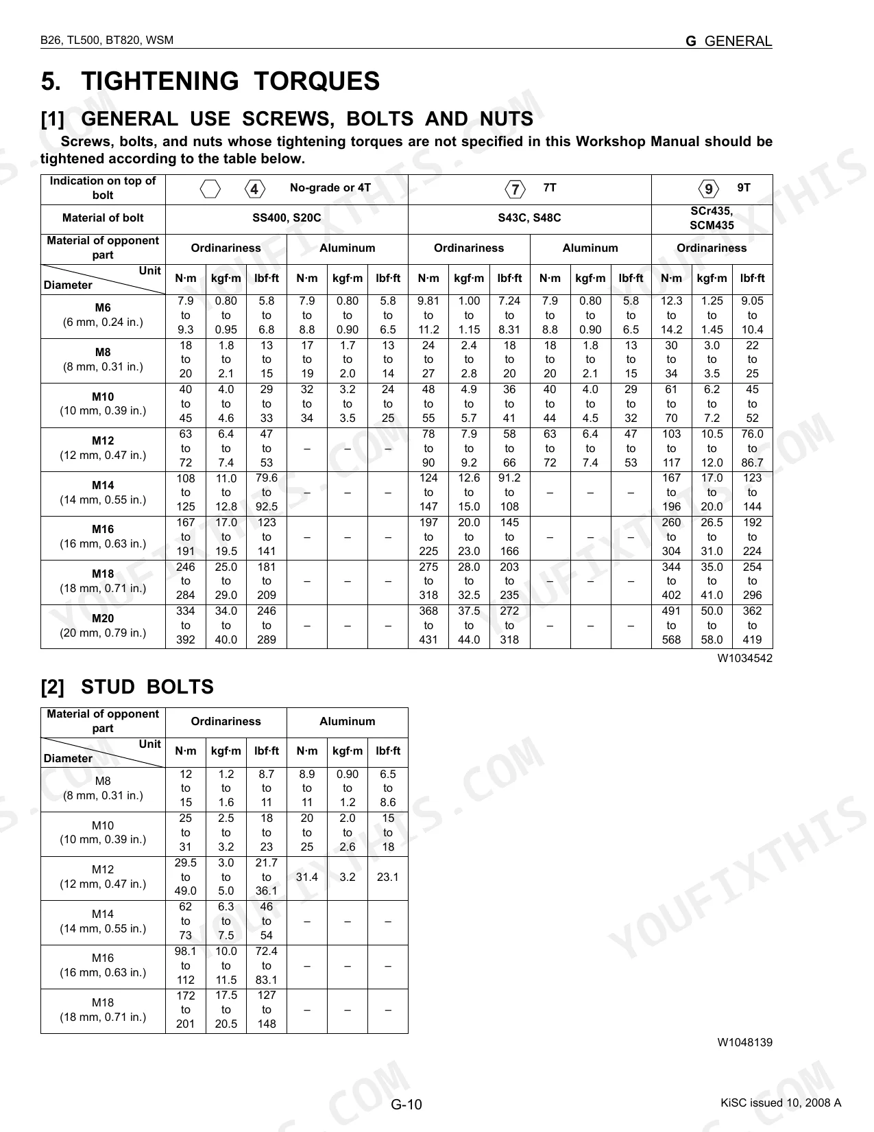
| G General | 13-66 | tractor identification, E3 engine, electrical parts handling, lubricants/fuel/coolant, tightening torques, scheduled maintenance intervals, special tools, tires, implement limitations |
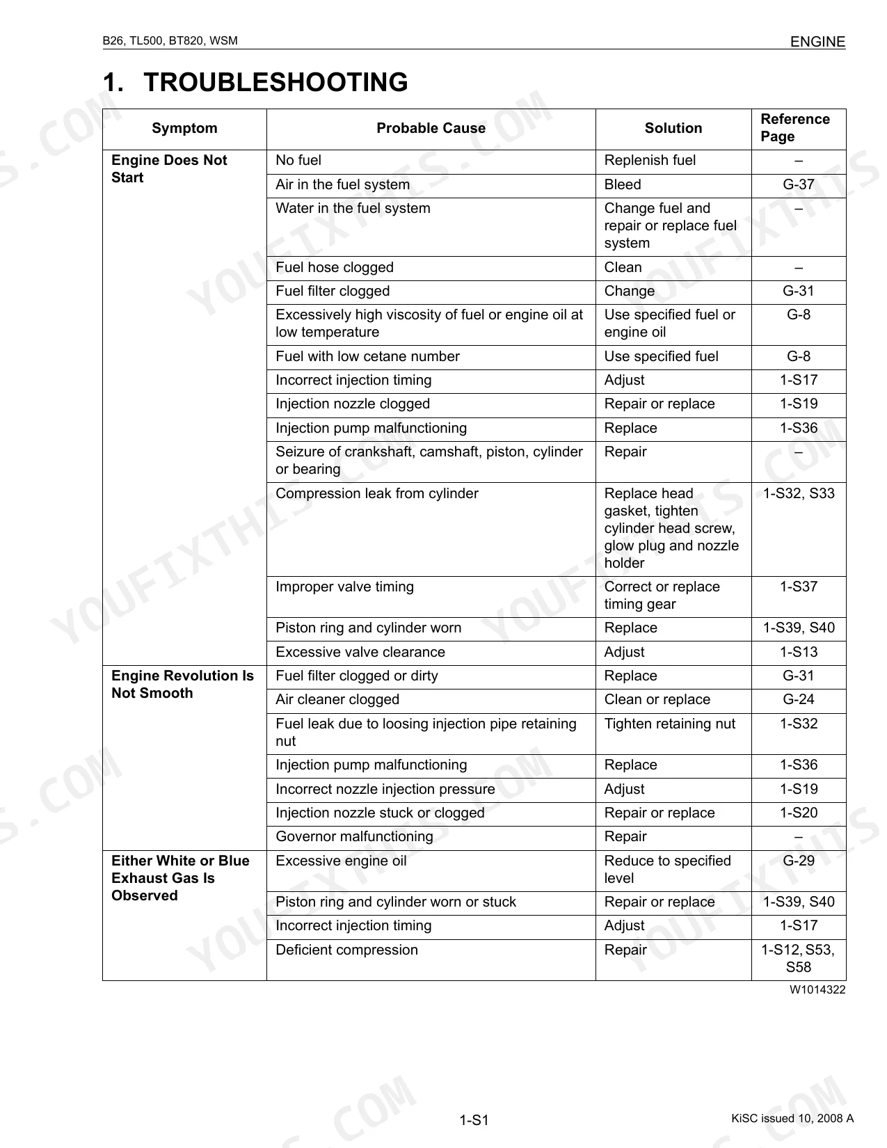
| 1 Engine | 67-128 | troubleshooting, servicing specifications, separating engine, checking and adjusting, disassembling and assembling, servicing internals |
| 2 Transmission | 129-199 | HST pump and motor, oil flow and valves, range gear shift, front wheel drive, differential lock, independent PTO clutch and hydraulic circuit, control linkage |
| 3 Rear Axle | 200-214 | structure, disassembling and assembling, servicing, rear axle torque specs |
| 4 Brakes | 215-226 | feature and operation, checking and adjusting, disassembling and assembling, servicing, brake specifications |
| 5 Front Axle | 227-246 | structure, separating front axle assembly, disassembling front axle assembly, checking and adjusting, servicing |
| 6 Steering | 247-262 | hydraulic circuit, steering controller, steering cylinder, relief valve checking, power steering controller disassembly, power steering cylinder servicing |
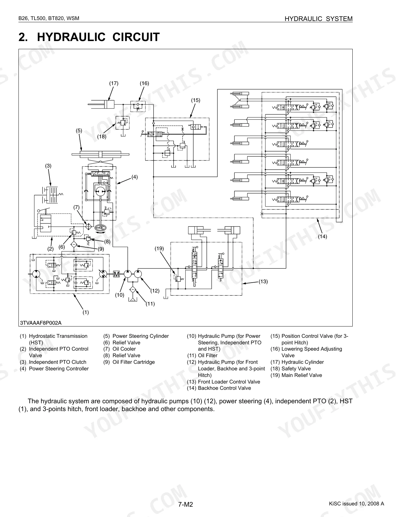
| 7 Hydraulic System | 263-307 | hydraulic pump, front loader control valve operation, 3-point hitch position control, feedback linkage, surge relief valve, lift arm adjustment, hydraulic cylinder disassembly |
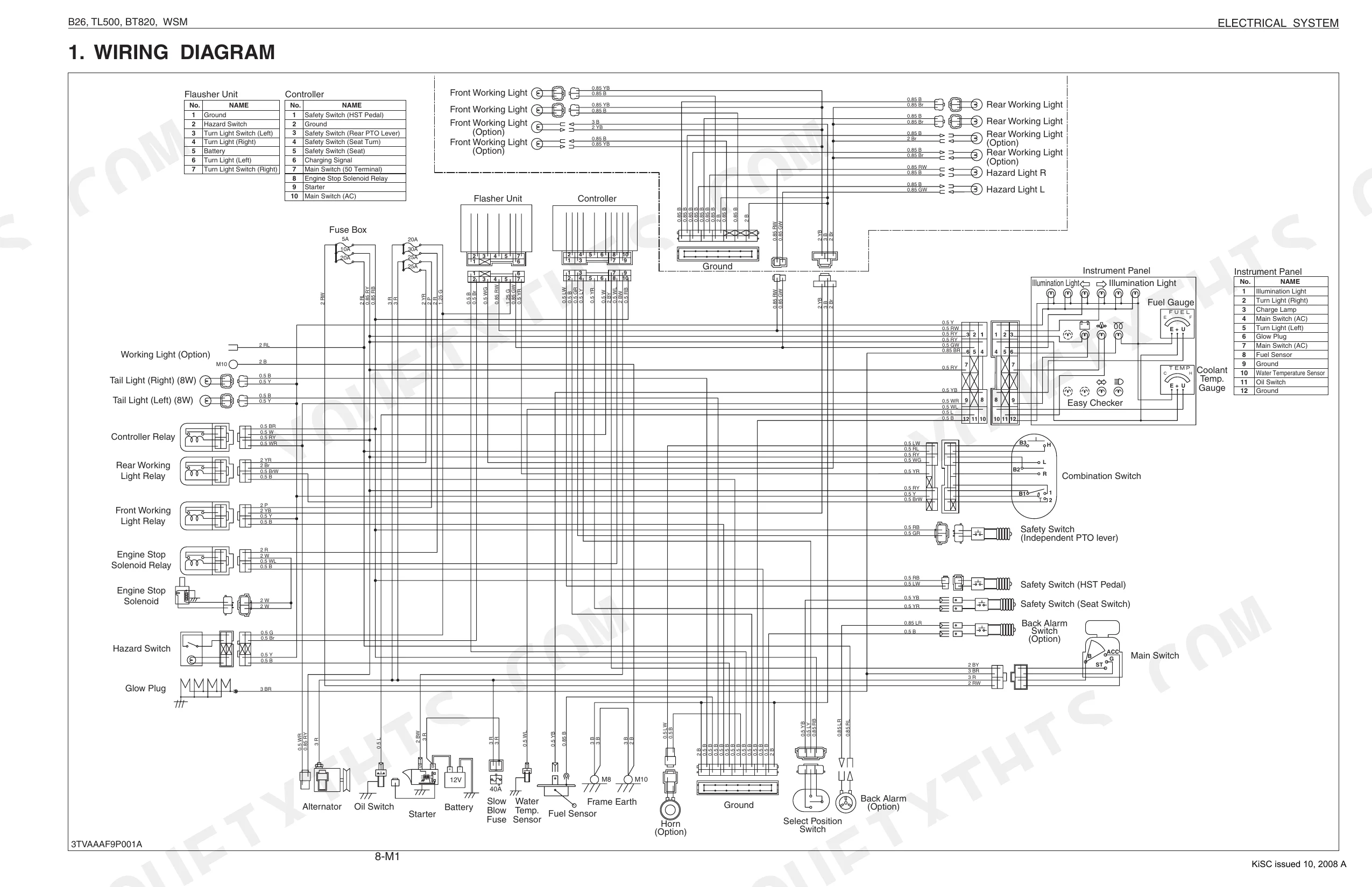
| 8 Electrical System | 308-349 | wiring diagram, OPC system circuit, engine starting and stopping, head/tail/turning lights, easy checker indication items, checking and adjusting |
| 9 Front Loader | 350-376 | front loader control valve and relief valve, boom and bucket cylinders, maintenance check list, dismounting and mounting, spill guard adjustment, loader identification |
| 10 Backhoe | 377-448 | hydraulic circuit, control valve, boom/dipperstick/bucket/swing/stabilizer cylinders, backhoe identification, dismounting and mounting, disassembling backhoe |
Quick Reference Specifications
| Specification | Value | Page |
|---|---|---|
| B26 | ||
| Main frame mounting bolt and nut (M16) tightening torque | 200 to 225 N·m | p. 37 |
| HST oil filter replacement interval | every 200 Hr | p. 27 |
| Engine oil filter tightening | Tighten filter by hand an additional 1/2 turn only | p. 33 |
| Fuel filter element replacement interval | every 400 Hr | p. 27 |
| Air cleaner primary element cleaning pressure | under 205 kPa (2.1 kgf/cm2, 30 psi) | p. 38 |
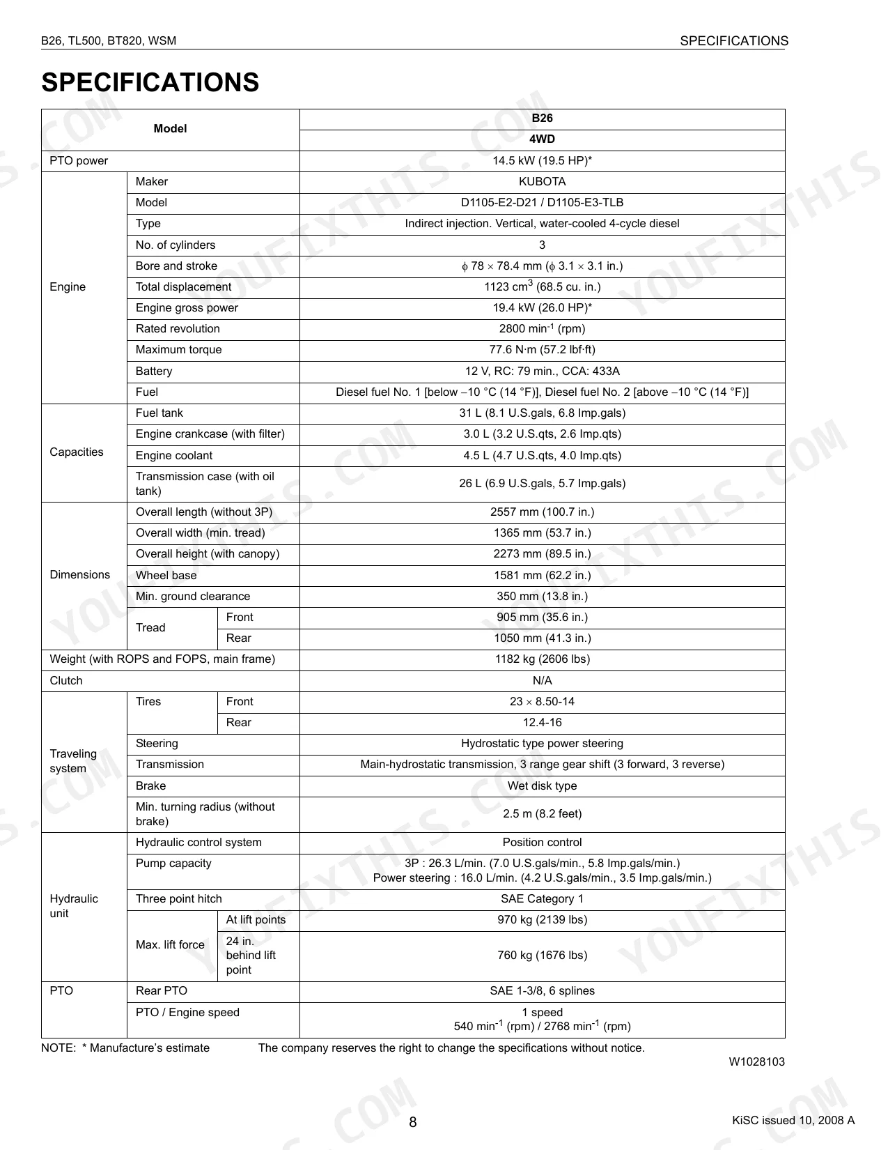
| Engine Oil Capacity (with filter) | 3.0 L (3.2 U.S.qts) | p. 10 |
| Fuel Tank Capacity | 31 L (8.1 U.S.gals) | p. 10 |
| TL500 | ||
| Bucket cylinder head mounting torque | 250 to 300 N·m | p. 366 |
| Boom Cylinder piston seal slide jig dimension (C) | 50.18 mm / 1.98 in. | p. 374 |
| BT820 | ||
| Stabilizer cylinder head tightening torque | 500 to 550 N·m | p. 432 |
| All Functions Inoperative (Front Loader Is OK) - Probable Cause | Quick coupler disconnected | p. 430 |
| All Models | ||
| Hydraulic hose fitting, flare nut (3/4) tightening torque | 36 to 40 N·m | p. 26 |
Kubota B26, TL500, BT820 Common Problems This Manual Covers
B26 loader lifts slow and weak once hot, with the boom drifting down under load p. 362
Check hydraulic oil level cold and top up with the correct grade. Replace the HST oil filter at the 200 hour interval listed on page 27. Inspect the suction strainer for debris. Test the front loader relief at 16.6 MPa (2402 psi) and rebuild the boom cylinder if internal bypass is confirmed.
Manual Section: Front Loader TroubleshootingBackhoe is dead on every function while the front loader still works normally p. 430
Verify the hydraulic quick coupler between tractor and backhoe is fully seated and locked, since a disconnected coupler is the listed probable cause on page 430. Wipe both halves clean, relieve residual pressure by cycling the joystick with engine off, then reconnect. Torque the stabilizer cylinder head to 500 to 550 N·m if you pull it for inspection.
Manual Section: Backhoe TroubleshootingDiesel hard to start, surges at idle, or lacks power under load with black exhaust
Drain water from the fuel separator and replace the fuel filter element at the 400 hour interval. Blow the air cleaner primary element clean with compressed air under 205 kPa (30 psi), from inside out. Set valve clearance cold to 0.145 to 0.185 mm. Bleed the fuel system after filter service.
Manual Section: Engine TroubleshootingMachine creeps poorly, loses drive when hot, or transmission oil overheats after long use
Verify transmission case fluid level against the 26 L capacity and watch for foaming that points to air ingestion. Measure HST charge relief pressure: it must hold 0.41 to 0.59 MPa at operating temperature. Swap the HST filter and clear the oil cooler fins. If charge pressure stays low after filter service, pull the charge pump and inspect for wear.
Manual Section: Transmission TroubleshootingBrakes pull to one side, drag, or feel weak on the pedal p. 220
Adjust brake pedal free travel to 30 to 40 mm at the linkage rod. Pull the brake covers and inspect linings for oil contamination from a leaking axle seal. Equalize left and right pedal travel within 5 mm of each other before locking the pedals together for road use. Replace linings as a pair, never one side only.
Manual Section: Brakes TroubleshootingSteering heavy, wanders, or wheel turns on its own with no input p. 253
Top up the hydraulic reservoir and bleed the steering circuit by cycling lock to lock five times with the engine at low idle. Set front axle toe-in between 0 and 10 mm with tires straight ahead. Tighten rear wheel mounting bolts to 196 to 225 N·m and confirm 138 kPa (20 psi) on 12.4-16 industrial rears before blaming the steering valve.
Manual Section: Steering TroubleshootingFrequently Asked Questions
How do I reset the hydraulic system on a Kubota B26?
If the 3-point hitch will not rise after long-term storage or a transmission oil change, bleed air from the system: turn the steering wheel right and left several times to restore hydraulic function. The manual warns against operating the tractor immediately after a transmission fluid change.
What are the torque specs for Kubota B26 wheel lugs / loader / backhoe bolts?
Front wheel mounting nuts: 77 to 90 N·m. Rear wheel mounting nuts: 167 to 191 N·m. TL500 boom cylinder head: 200 to 230 N·m. BT820 boom, swing, and bucket cylinder heads: 250 to 280 N·m. BT820 dipperstick cylinder head: 350 to 400 N·m.
What are the replacement specifications for Hydraulic filter?
Replace the HST oil filter after the first 50 hours, then every 200 hours. Use only a KUBOTA genuine filter to avoid serious damage to the hydraulic system. After the new filter contacts the mounting surface, tighten it by hand an additional 1/2 turn.
What are the replacement specifications for Engine oil filter?
Replace the engine oil filter after the first 50 hours, then every 200 hours. Use a KUBOTA genuine filter to prevent serious engine damage. Coat the rubber seal with clean engine oil, then tighten by hand an additional 1/2 turn after the filter contacts the mounting surface.
Is this Kubota B26, TL500, BT820 Workshop Manual a digital download?
Yes, a 448-page searchable PDF ready for immediate download. Pull it up on your phone at the machine. No shipping, no waiting.
Are there any print restrictions on this Kubota B26, TL500, BT820 manual?
None. The PDF has no DRM, so print any page or section you need on a standard printer.
Are hydraulic system diagrams in this Kubota B26, TL500, BT820 Workshop Manual?
Yes. Hydraulic system diagrams, circuit schematics, and component specifications are all included.
Document Quality
This is a native digital PDF, not a scan, so the full text is searchable and you can easily copy and paste content. The text is sharp and easy to read, and the numerous diagrams, schematics, and illustrations are high-quality with clear, legible labels. All pages are clean and free of any marks or scan artifacts, with a few blank pages used as intentional dividers between major sections.


Reviews
There are no reviews yet.