


Part of the Kubota Parts Manuals.
This is the parts catalog for the Kubota B20 compact tractor, 251 pages of exploded diagrams and part numbers. It works from the engine crankcase, oil pan, piston and crankshaft, cylinder head and injection pump through the cooling and fuel systems, the dynamo, starter and battery, then the clutch, HST transmission, shafts, axles, brakes and the hydraulic lift circuit.Every assembly pairs a diagram with reference numbers, Kubota part numbers, descriptions and quantities, with serial number and interchangeability notes so you order the right component for your tractor. It is the reference for identifying wear parts and matching replacements on the B20.Whether you need a fuel filter, an air cleaner element, an HST part, a hydraulic gear pump component or a radiator, you can confirm the exact number before buying. Download the PDF after purchase and print the diagram pages you need at the bench.
What's Inside This Kubota B20 Parts Manual
| System | Pages | Key Topics |
|---|---|---|
| Clutch & Transmission | Clutch, Clutch Rod, Clutch Pedal, Clutch Housing, Transmission Case, Transmission Case Cover, HST, 1St Shaft/2Nd Shaft, 3Rd Shaft, 4Th Shaft, Neutral Holder, Speed Change Plate, Hi-Lo Gear Shift Lever, Hi-Lo Gear Shift Fork | |
| Fuel System | Nozzle Holder, Fuel Camshaft, Injection Pump, Engine Stop Lever, Speed Control Plate, Governor, Air Cleaner, Engine Stop Rod, Accelerator Lever, Fuel Tank, Fuel Pipe 1, Fuel Filter, Fuel Pipe 2, Speed Control Pedal | |
| Cooling System | Water Pump, Water Flange/Thermostat, Fan, Water Pipe, Radiator | |
| Engine | Crankcase, Oil Pan, Piston/Crankshaft, Main Bearing Case, Flywheel, Cylinder Head, Valve/Rocker Arm, Cylinder Head Cover, Inlet Manifold, Exhaust Manifold, Camshaft, Gear Case, Muffler, Bevel Gear Case | |
| Electrical System | Dynamo, Starter, Battery, Light, Panel/Switch, Wire Harness, Rear Working Light, Front Working Light | |
| PTO | PTO Shaft, Front Wheel Drive Lever/PTO Lever, PTO Fork Shaft | |
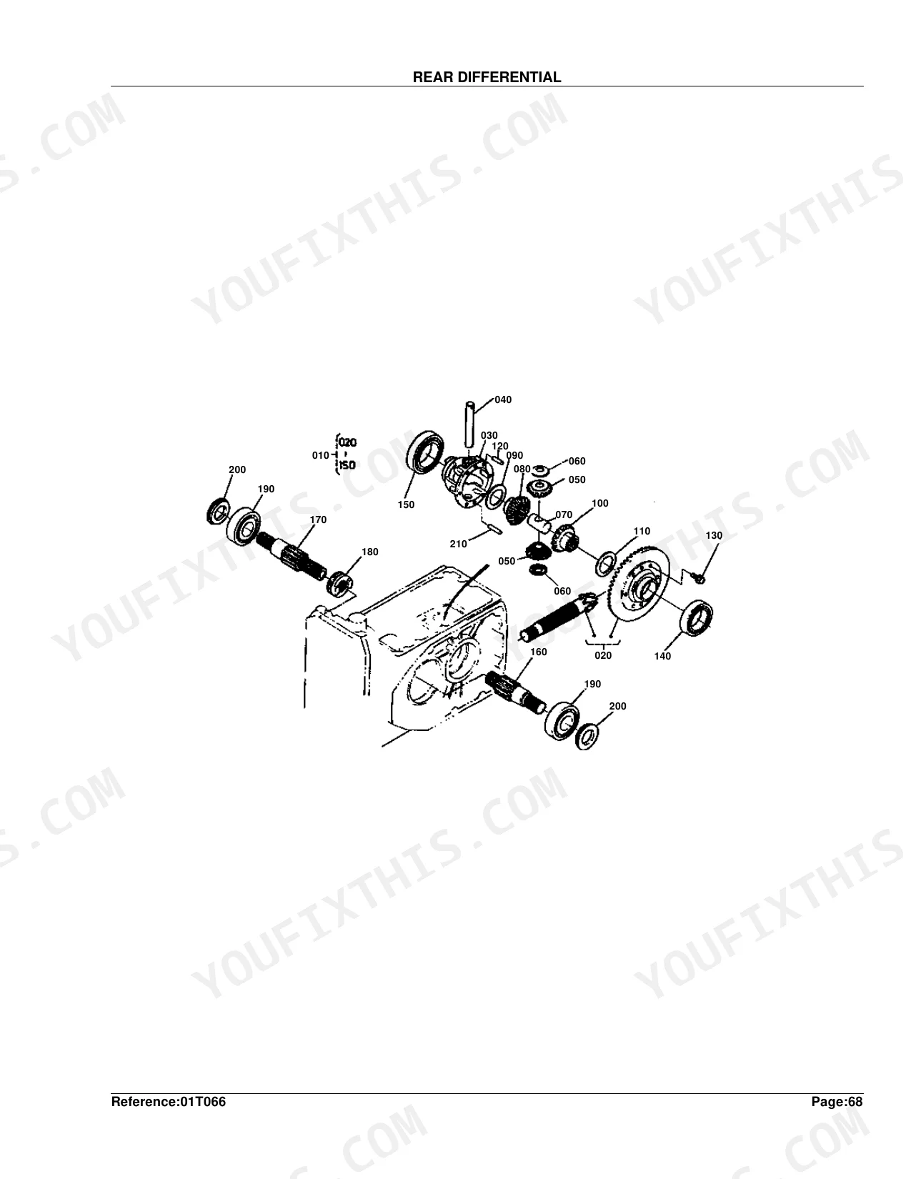
| Rear Axle, Differential & Brakes | Rear Differential, Rear Axle, Rear Axle Case, Brake, Brake Rod, Brake Pedal, Front Axle Case | |
| Front Axle & Steering | Propeller Shaft, Front Drive Shaft/6Th Shaft, Front Drive Fork, Front Axle Arm, Front Differential, Front Drive Shaft, Front Axle Frame, Knuckle Arm/Tie Rod, Power Steering | |
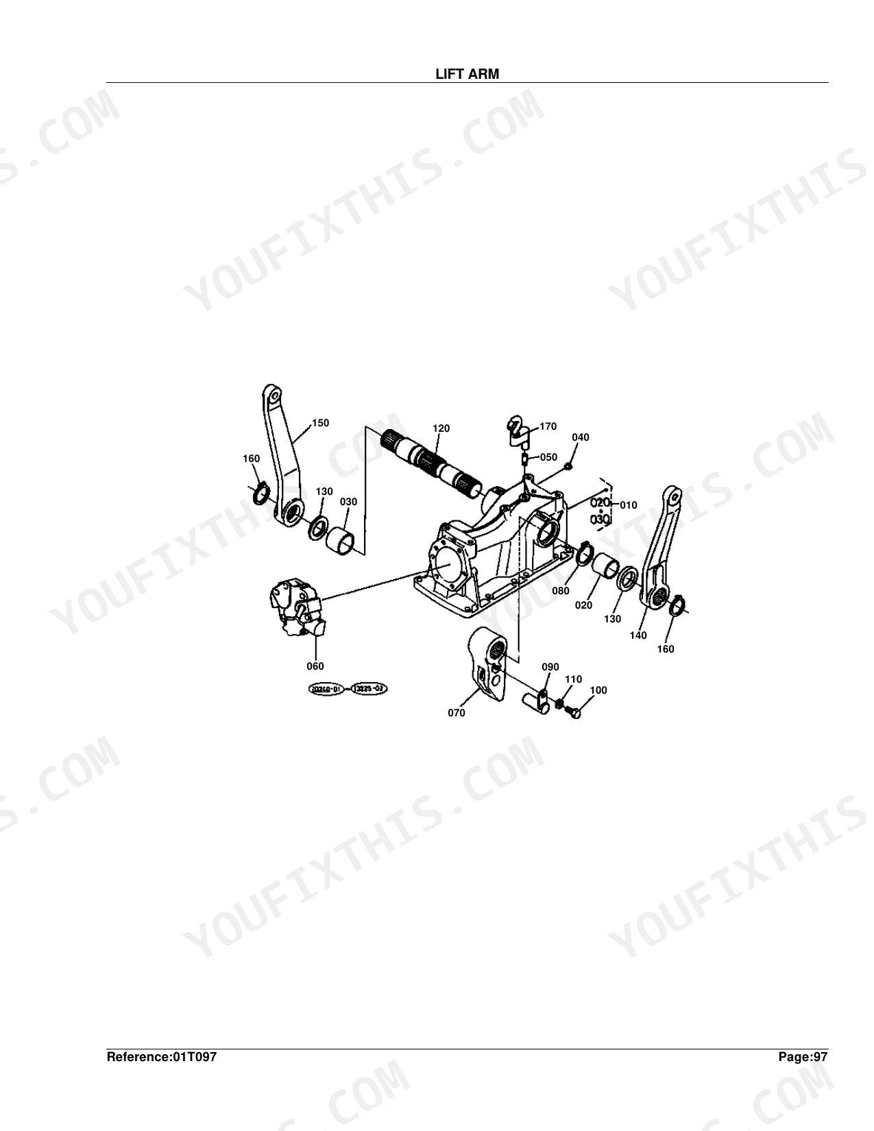
| Hydraulics & 3-Point Hitch | Hydraulic Gear Pump, Hydraulic Pipe, Hydraulic Block, Lift Arm, Hyd.Cylinder Cap, Control Valve, Control Valve 1, Control Valve 2, Control Valve 3, Top Link, Lower Link / Lift Rod, Top Link Bracket | |
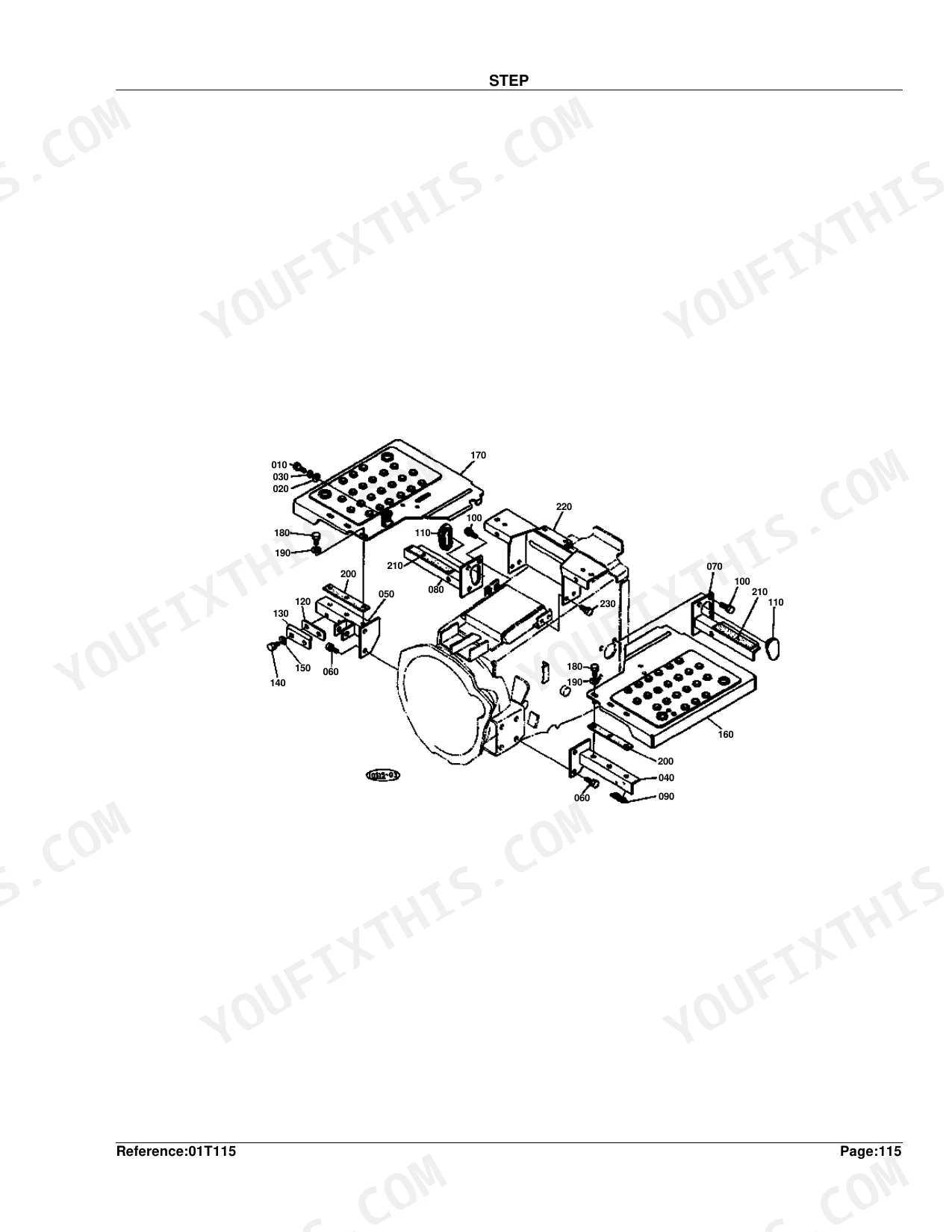
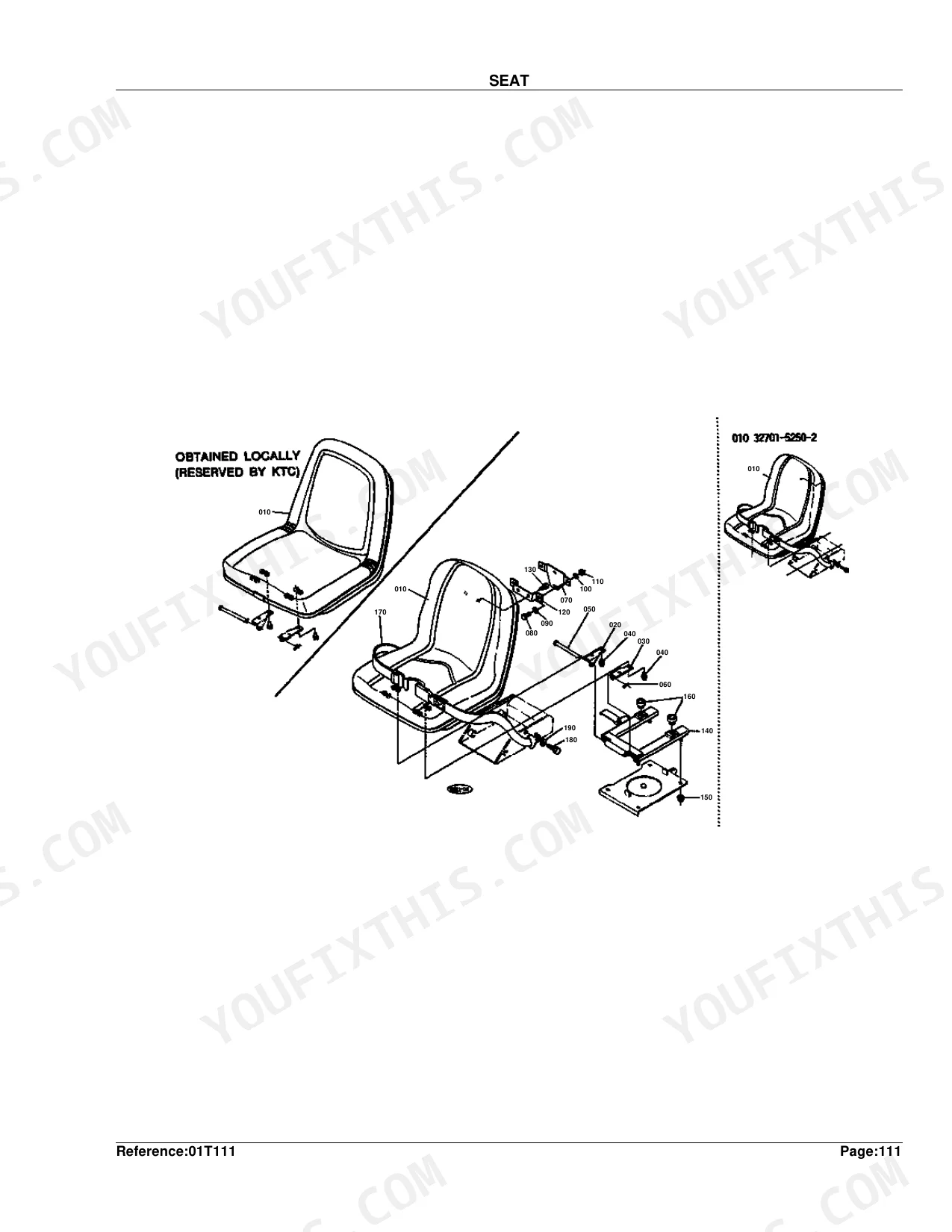
| Body & Operator Station | Main Frame, Hood, Hood Cover Rear, Front Grille, Fender, Seat, Seat Turn Table, Seat Base, Seat Plate, Step, ROPS, FOPS | |
| Decals & Accessories | Label 1, Label 2, Accessories and Service Parts | |
| Other Components | Release Lever, 7Th Shaft, Diff.Lock Pedal, Rear S.S. Sure Grip Tire, Rear Ind.Sure Grip Tire, Bevel Gear Shaft, Front Sure Grip Tire, Check Chain |
Quick Reference Specifications
| Specification | Value | Page |
|---|---|---|
| Fuse Rating | 15A | p. 95 |
| Piston Oversize | +0.5MM | p. 11 |
| Metal Crankpin Undersize | -0.2MM | p. 11 |
| Nozzle Holder Adjusting Washer Thickness (Min) | 1.00MM | p. 23 |
| Nozzle Holder Adjusting Washer Thickness (Max) | 1.95MM | p. 23 |
| Injection Pump Shim Thickness | 0.15MM | p. 41 |
| Wire Harness Fuse Rating | 15A | p. 95 |
| HST Gear Tooth Count | 17T | p. 107 |
| 1st Shaft Gear Tooth Count | 16T | p. 114 |
| Rear Differential Bevel Gear Ratio | 6-37T | p. 142 |
| Rear Axle Gear Tooth Count | 60T | p. 146 |
| Rear Tire Size | 12.4-16 | p. 149 |
Kubota B20 Common Problems This Manual Covers
Engine will not start
A B20 that cranks but will not start usually comes down to fuses, wiring or the key switch rather than one failed part. The Wire Harness section shows the harness and fuse with their part numbers.
Manual Section: Wire Harness p. 94Hard starting or low power
Hard starting and low power often trace to a clogged air cleaner element restricting airflow. The Air Cleaner section identifies the element and housing parts for replacement.
Manual Section: Air Cleaner p. 62Slow or weak hydraulic lift
Slow or weak hydraulic lift points to a worn hydraulic gear pump. The Hydraulic Gear Pump section and its component-parts diagram list the pump parts to order.
Manual Section: Hydraulic Gear Pump p. 58Overheating during heavy work
Overheating during heavy work usually means a blocked or leaking radiator. The Radiator section lists the radiator and related cooling parts.
Manual Section: Radiator p. 82Poor drive or weak creep speed
Poor drive or weak creep speed on the hydrostatic B20 is often HST wear. The HST section and its component-parts diagram identify the transmission parts.
Manual Section: HST p. 106Battery will not hold a charge
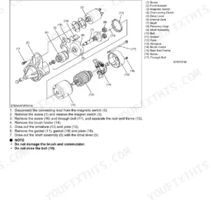
A tractor that will not hold a charge often has a worn dynamo. The Dynamo section shows the dynamo and its component parts with numbers.
Manual Section: Dynamo p. 52Frequently Asked Questions
What does this parts catalog cover?
It is the Kubota B20 compact tractor parts catalog, covering the diesel engine, fuel and cooling systems, electrical parts, HST transmission, front and rear axles, brakes and hydraulics.
Does it list Kubota part numbers?
Yes. Each assembly pairs an exploded diagram with reference numbers, Kubota part numbers, descriptions and quantities so you can order the correct B20 part.
Where are the hydraulic parts?
The Hydraulic Gear Pump section and its component-parts diagram cover the pump, and later hydraulic pipe, control valve and lift arm sections cover the rest of the lift circuit. p. 58
Does it include the engine parts?
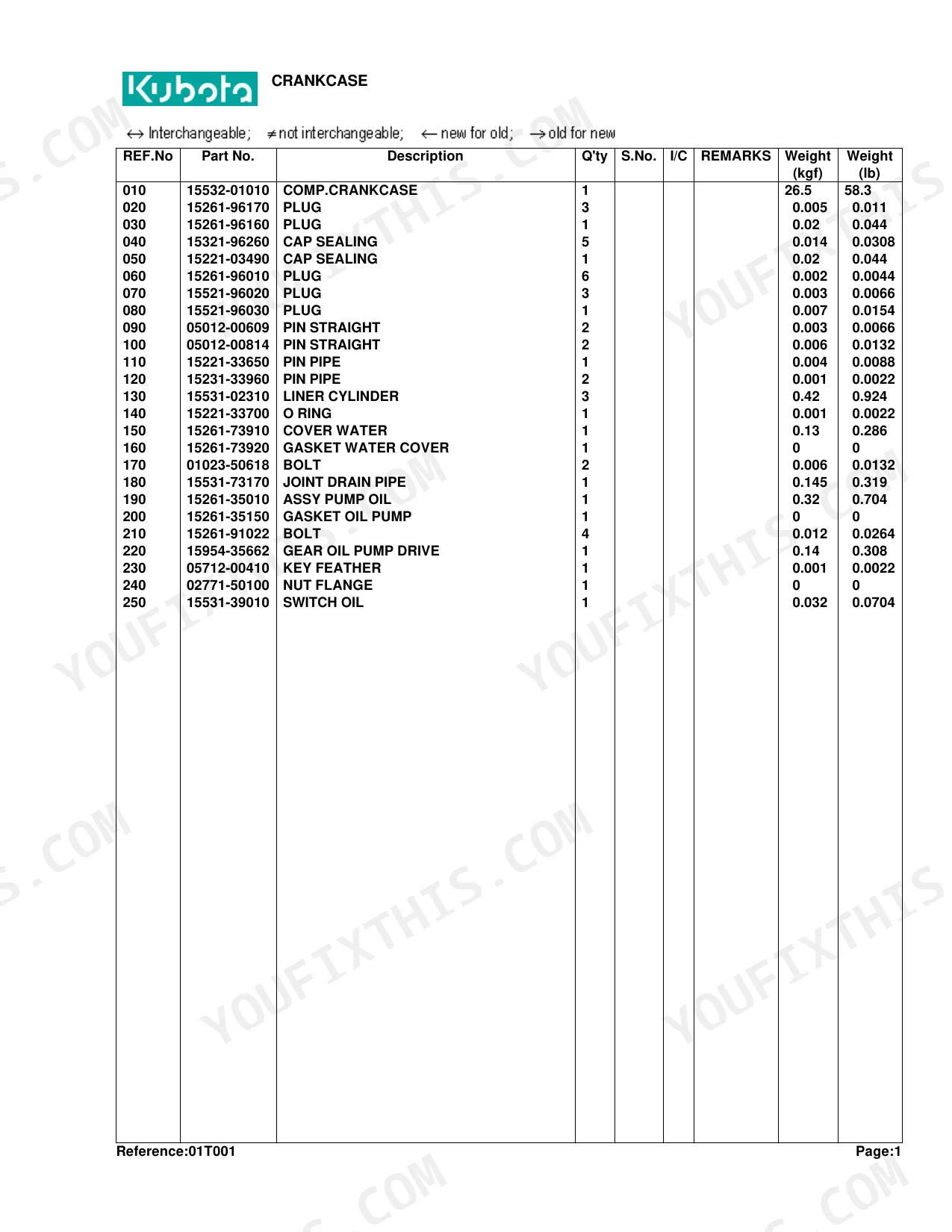
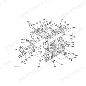
Yes. Sections from the Crankcase through the Piston/Crankshaft and Cylinder Head cover the engine parts; the Crankcase section begins the engine breakdown. p. 6
How will I receive this Kubota B20 Parts Manual?
Right after payment clears, the full 251-page searchable Parts Manual downloads as a PDF. Open it on a laptop, tablet, or phone out in the shop.
Can I print this manual?
Yes, with no restrictions. The PDF is DRM-free, so print whatever sections you want to carry out to the shop. Standard letter or A4 paper both work fine.
Can I find hydraulic circuit diagrams in this Kubota B20 manual?
This is a parts catalog. It includes detailed exploded-view diagrams for hydraulic components, including pumps, valves, and piping, with OEM part numbers showing how assemblies fit together. It does not contain hydraulic circuit schematics or flow diagrams; those live in the B20 service/workshop manual.


Reviews
There are no reviews yet.