
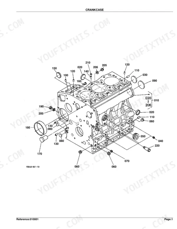
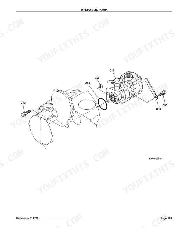
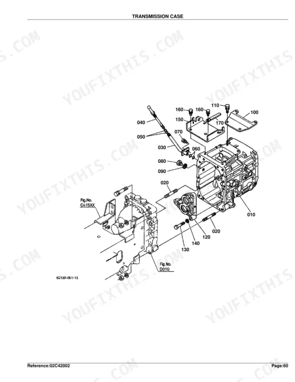
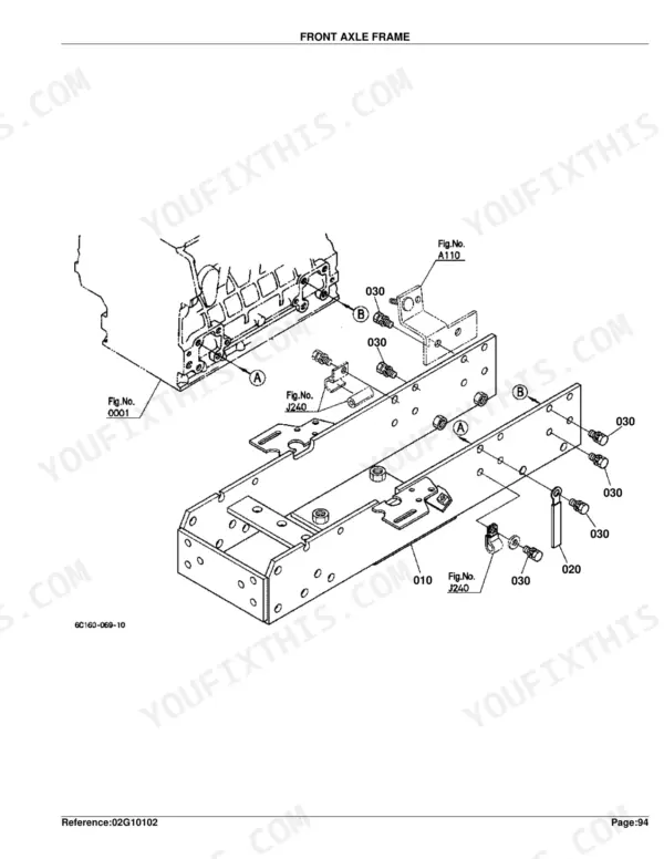
Part of the Kubota Parts Manuals.
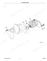
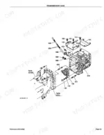
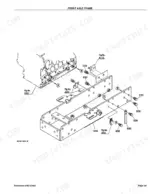
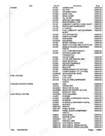
This is the Kubota B7510HSD parts catalog, publication 100K0780, a 348-page illustrated guide to every component on this compact 4WD hydrostatic diesel tractor. It is organized as exploded diagrams paired with numbered parts lists, so you can find the exact part number, quantity, and serial-range notes before ordering.
Coverage runs the full machine: engine internals, fuel and cooling systems, the hydrostatic transmission and its HST component parts, clutch, front and rear axles, brakes, steering, electrical wiring, and body panels. Country-code and interchangeability columns tell you which part fits your serial number.
Use it to identify the right replacement for a repair, confirm a superseded part, or plan an overhaul with confidence. This PDF download is searchable and printable, covering serial ranges including 4E9526, 4G0001, 3Y9499, and 4A0001.
What's Inside This Kubota B7510HSD Parts Manual
| System | Pages | Key Topics |
|---|---|---|
| Clutch & Transmission | Clutch, Clutch Rod, Clutch Pedal, Clutch Housing, Transmission Case, Clutch Shaft, HST, Range Gear Shift Fork, PTO Gear Shift Fork, Differential Lock Shift Fork, Neutral Holder Link, Range Gear Shift Lever, PTO Gear Shift Lever | |
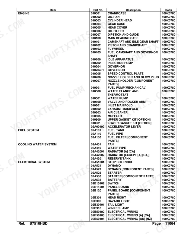
| Fuel System | Fuel Camshaft and Governor Shaft, Idle Apparatus, Injection Pump, Governor, Speed Control Plate, Nozzle Holder and Glow Plug, Nozzle Holder, Fuel Pump, Air Cleaner, Accelerator Lever, Fuel Tank, Fuel Pipe, Fuel Filter, Stop Solenoid, Speed Control Pedal | |
| Cooling System | Water Flange and Thermostat, Water Pump, Fan, Water Pipe, Radiator, Reserve Tank | |
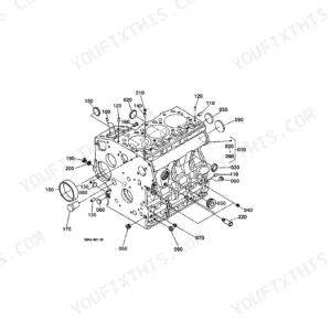
| Engine | Crankcase, Oil Pan, Cylinder Head, Head Cover, Oil Filter, Dipstick and Guide, Main Bearing Case, Camshaft and Idle Gear Shaft, Piston and Crankshaft, Flywheel, Valve and Rocker Arm, Inlet Manifold, Exhaust Manifold, Muffler, Upper Gasket Kit, Lower Gasket Kit | |
| Electrical System | Dynamo, Starter, Battery, Switch, Panel Board, Hazard Light, Tail Light, Winker Lamp, Electrical Wiring, Alternator Kit, Alternator, Warking Light Kit, Horn Kit, Brake Lamp Kit | |
| PTO | PTO Protector | |
| Rear Axle, Differential & Brakes | Rear Axle Case, Rear Axle, Brake, Brake Rod, Parking Brake Lever, Brake Pedal, Front Axle Case, Rear Wheel | |
| Front Axle & Steering | Front Wheel Drive Lever, Front Axle Frame, Front Axle, Steering Handle, Steering Post, Front Wheel | |
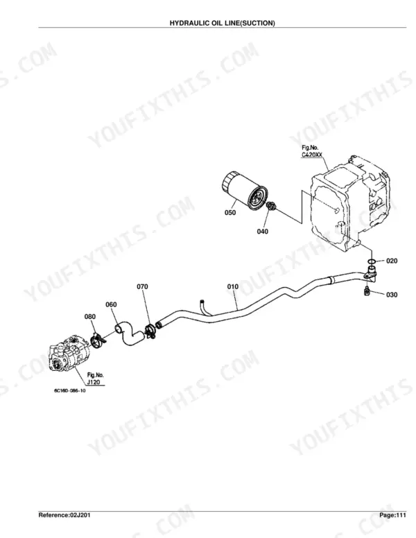
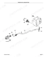
| Hydraulics & 3-Point Hitch | Hydraulic Control Lever, Hydraulic Pump, Hydraulic Oil Line, Hydraulic Cylinder, Feed Back Lever, Control Valve, Point Linkage 2, Lower Link, Point Linkage 1, Drawbar, Rear Hitch | |
| Body & Operator Station | Front Grille, Bonnet, ROPS | |
| Decals & Accessories | Label, Accessories and Service Parts | |
| Other Components | Head Right, Speed Set Lever, Check Chain |
Quick Reference Specifications
| Specification | Value | Page |
|---|---|---|
| FUSE | 30A | p. 113 |
| FUSE AUTO | 5A | p. 113 |
| Engine Crankcase Weight | 32.5 kgf | p. 8 |
| Cylinder Head Weight | 8.72 kgf | p. 12 |
| Oil Filter Weight | 0.35 kgf | p. 18 |
| Piston Weight (STD) | 0.4 kgf | p. 26 |
| Flywheel Weight | 17.2 kgf | p. 28 |
| Injection Pump Weight | 1 kgf | p. 35 |
| Radiator Weight | 2.5 kgf | p. 79 |
| Clutch Disk Weight | 0.88 kgf | p. 119 |
Kubota B7510HSD Common Problems This Manual Covers
HST loses forward and reverse drive
A sudden loss of movement with no response from the HST pedal is a common B7510 complaint. The HST component parts diagrams identify the pump, motor, and seal part numbers you need to order for a repair or rebuild.
Manual Section: HST [Component Parts] p. 140Weak or slow hydraulics when cold
Hydraulic response can be sluggish until the machine warms up, pointing to fluid, filter, or HST wear. The transmission case section shows the HST, shafts, and related assemblies with their part numbers.
Manual Section: Transmission Case p. 128No-start or intermittent cranking
Weak or failing starter and solenoid parts cause no-start and intermittent cranking. The starter section and its component parts diagram give the exact numbers for a replacement or rebuild kit.
Manual Section: Starter p. 91Sudden shutdown from safety switch
Interlock or safety switch faults can shut the tractor down or block starting. The switch section lists the switch assemblies and their part numbers so you can replace the failed unit.
Manual Section: Switch p. 98Overheating from a clogged radiator
Blocked fins or a failing radiator cause overheating under load. This section shows the radiator assembly and hardware so you can order the correct core and mounting parts.
Manual Section: Radiator [a] [Ca] p. 78Blown fuses or electrical faults
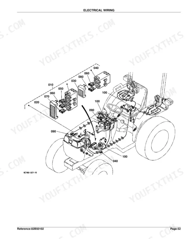
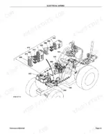
Intermittent accessories and dashboard functions often trace to a blown fuse or corroded connection. The electrical wiring section covers the harness, fuse holder, and fuse ratings of 30A plus 5A, 10A, 20A, and 30A auto fuses.
Manual Section: Electrical Wiring p. 112Frequently Asked Questions
Which model does this catalog cover?
It covers the Kubota B7510HSD compact tractor under publication number 100K0780, including serial ranges such as 4E9526, 4G0001, 3Y9499, and 4A0001.
Is this a repair manual or a parts catalog?
It is a parts catalog. It gives exploded diagrams and numbered parts lists for ordering replacements, not step-by-step repair or torque procedures.
Where do I find the hydrostatic transmission parts?
The transmission case section shows the HST and related shafts, and the HST component parts diagrams break the unit down into individual numbered parts. p. 140
Does it list the fuse ratings?
Yes. The electrical wiring section lists a 30A main fuse plus 5A, 10A, 20A, and 30A auto fuses with their part numbers. p. 113
Is this Kubota B7510HSD Parts Catalog a digital download?
Yes. The 348-page searchable PDF downloads right after checkout, ready to open on a laptop, tablet, or phone out in the shop.
Can I print this manual?
Yes. Print individual pages or full chapters for your own shop use, on letter or A4 paper.


Reviews
There are no reviews yet.