
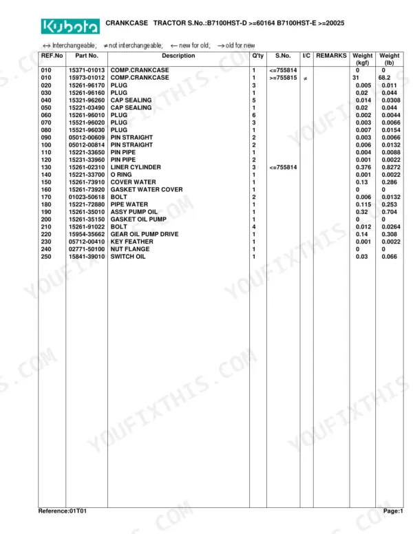
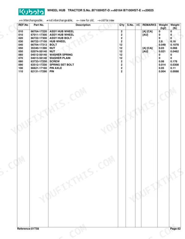
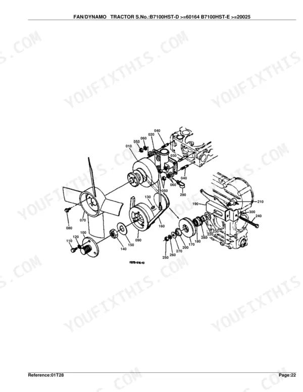
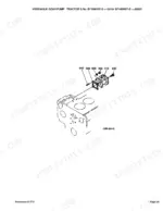
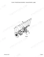
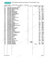
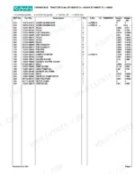
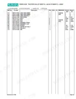
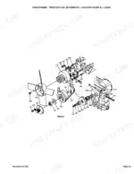
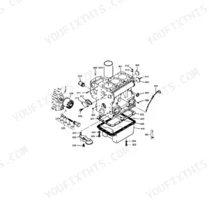
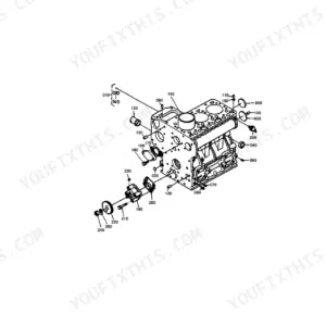
Part of the Kubota Parts Manuals.
This is the factory parts catalog for the Kubota B7100HST-D and B7100HST-E compact tractors, the 4WD and 2WD versions of the same hydrostatic machine. It runs 180 pages of exploded diagrams paired with Kubota part numbers, quantities, and serial-number applicability (B7100HST-D from serial 60164, B7100HST-E from serial 20025).
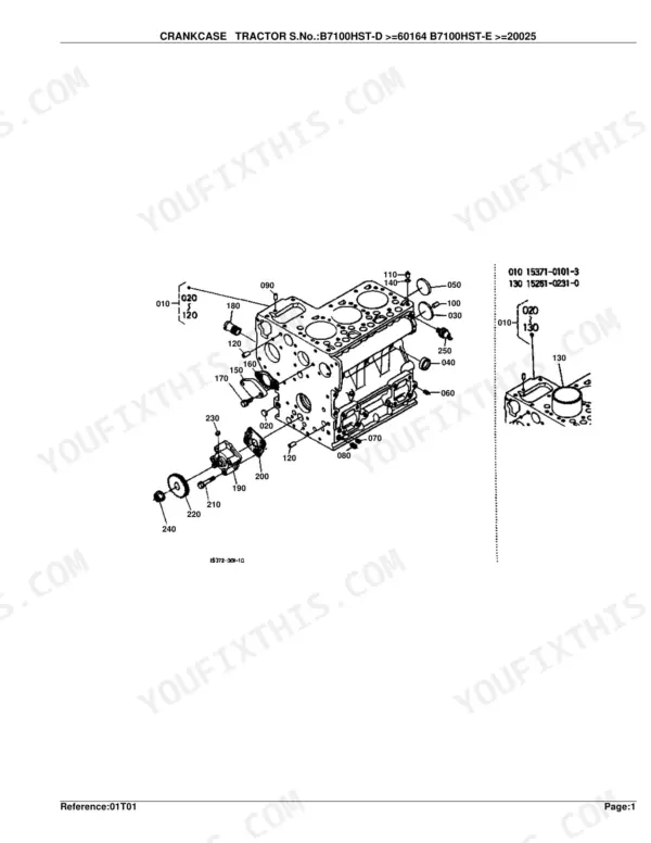
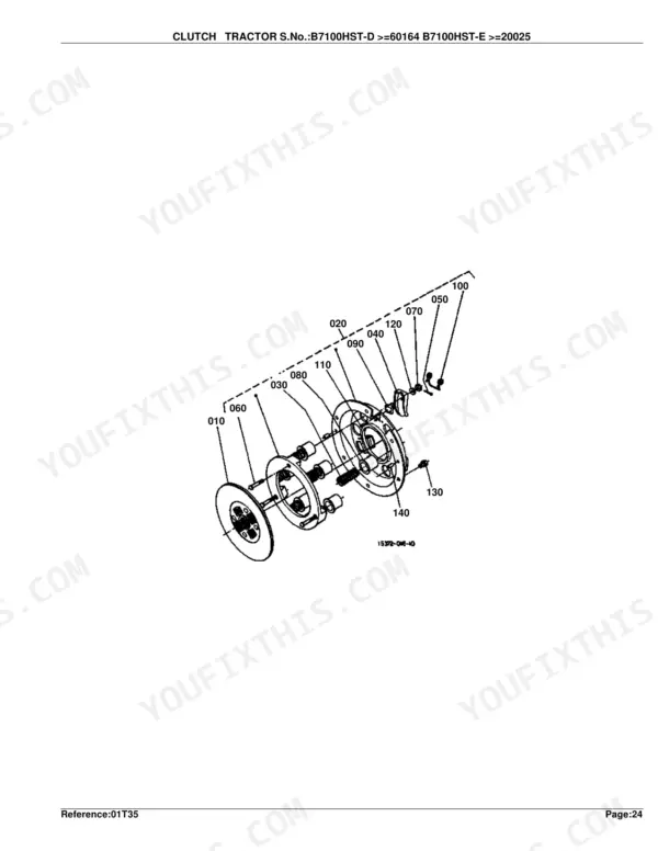
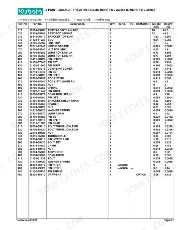
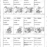
Every assembly is broken out: the diesel engine, HST drive, clutch and transmission shafts, front axle and 4WD drivetrain, steering, brakes, hydraulic gear pump, control valve, and three-point linkage, plus sheet metal, electrical components, and labels.
Use it to identify the exact replacement part before you order, cross-check interchangeability between serial ranges, and see how each group fits together during a rebuild. Delivered as a downloadable PDF you can search, zoom, and print.
Other editions of this manual
- Kubota B7100HST-D Parts Catalog Original price was: $44.99.$29.99Current price is: $29.99.
- Kubota B7100HST-E Parts Catalog Original price was: $43.99.$29.99Current price is: $29.99.
What's Inside This Kubota B7100HST-D, B7100HST-E Parts Manual
| System | Pages | Key Topics |
|---|---|---|
| Clutch & Transmission | Clutch, Clutch Rod, Clutch Pedal, Clutch Housing, Transmission Case, HST, 2Nd Shaft, 3Rd Shaft/5Th Shaft, 4Th Shaft, Neutral Holder, Speed Change Plate, Hi-Lo Gear Shift Lever, PTO Gear Shift Lever | |
| Fuel System | Nozzle Holder, Fuel Pump, Injection Pump, Speed Control Plate, Governor, Air Cleaner, Accelerator Rod, Fuel Tank/Accelerator Lever, Fuel Filter, Speed Control Pedal | |
| Cooling System | Fan/Dynamo, Radiator/Oil Cooler | |
| Engine | Crankcase, Oil Pan, Piston/Crankshaft, Main Bearing Case, Flywheel, Cylinder Head, Valve/Rocker Arm, Cylinder Head Cover, Inlet Manifold, Exhaust Manifold, Camshaft, Gear Case, Upper Gasket Kit, Lower Gasket Kit, Muffler, Front Gear Case | |
| Electrical System | Dynamo, Starter, Battery, Light | |
| PTO | PTO Cover, Rear PTO, Mid PTO | |
| Rear Axle, Differential & Brakes | Rear Differential, Rear Axle, Rear Axle Case, Brake, Brake Rod/Pedal | |
| Front Axle & Steering | Propeller Shaft, Front Wheel Drive Shaft, Front Wheel Hub, Front Axle Arm, Front Differential, Front Drive Shaft, Front Drive Lever, Front Wheel Support, Knuckle Arm, Steering | |
| Hydraulics & 3-Point Hitch | Hydraulic Gear Pump, Hydraulic Pipe 1, Hydraulic Pipe 2, Lift Arm, Hyd.Cylinder Cap, Control Valve, 3-Point Linkage | |
| Body & Operator Station | Panel, Case Cover, Hood, Fender, Seat, Step | |
| Decals & Accessories | Label 1, Label 2, Accessories and Service Parts | |
| Other Components | Wheel Hub |
Quick Reference Specifications
| Specification | Value | Page |
|---|---|---|
| WASHER ADJUSTING clearance | 1.00MM | p. 23 |
| COLLAR ADJUSTING clearance | 1.515 TO 1.535MM | p. 154 |
| Crankshaft Assembly Weight | 8 kgf / 17.6 lb | p. 11 |
| Cylinder Head Assembly Weight | 9.2 kgf / 20.24 lb | p. 17 |
| Nozzle Holder Adjusting Washer Thickness | 1.00MM | p. 23 |
| Injection Pump Assembly Weight | 2.16 kgf / 4.752 lb | p. 37 |
| Dynamo Assembly Weight | 1.7 kgf / 3.74 lb | p. 49 |
| Clutch Disk Assembly Weight | 0.93 kgf / 2.046 lb | p. 53 |
| Air Cleaner Body Weight | 0.69 kgf / 1.518 lb | p. 61 |
| Radiator Assembly Weight | 6 kgf / 13.2 lb | p. 71 |
| Battery Assembly Weight | 9.3 kgf / 20.46 lb | p. 77 |
| Clutch Housing Weight | 21 kgf / 46.2 lb | p. 87 |
Kubota B7100HST-D, B7100HST-E Common Problems This Manual Covers
HST loses drive under load
Hydrostatic tractors can stop moving, creep weakly, or lose drive when fluid is low, the suction screen is clogged, or the HST pump and motor wear internally. The HST group shows every internal part for inspection or overhaul.
Manual Section: HST p. 94Recurring hydraulic leaks after repair
Leaks return around the hydraulic control valve if the gaskets, O-rings, and worn ball, seat, and spring parts are not renewed during service. This group breaks out each of those wear parts.
Manual Section: Control Valve p. 163Steering turns heavy or inconsistent
Power steering effort climbs when linkage wears or the hydraulic feed is compromised. The steering group identifies the column, gear, and linkage parts owners replace to restore feel.
Manual Section: Steering p. 153No-start or intermittent shutdown
Owners trace dead cranks and random shutdowns to blown fuses, bad relays, a faulty fuel shutoff solenoid, or a worn key switch. The starter group covers the starter and its component parts for these checks.
Manual Section: Starter p. 72Front axle looseness and steering play
Wear in the tie rods, pivot, and front axle joints produces excess play and poor alignment on 4WD models. The front axle arm group shows the pivot and support parts involved.
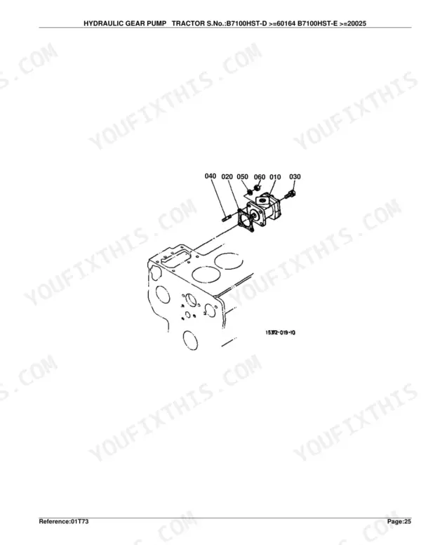
Manual Section: Front Axle Arm p. 141Weak lift or slow hydraulics
A worn hydraulic gear pump reduces lift and hydraulic performance. This group details the pump and its component parts so you can order a rebuild kit or complete assembly.
Manual Section: Hydraulic Gear Pump p. 54Frequently Asked Questions
Which tractors does this catalog cover?
It covers the Kubota B7100HST-D (4WD) and B7100HST-E (2WD) compact tractors, the two versions of the same hydrostatic model, across 180 pages of parts diagrams. Parts apply from serial B7100HST-D 60164 and B7100HST-E 20025.
Does it show the hydrostatic transmission parts?
Yes. The HST group provides exploded diagrams and part numbers for the hydrostatic transmission and its component parts, useful when diagnosing lost or weak drive. p. 94
Will it help me find hydraulic control valve parts?
Yes. The control valve section breaks out the valve body along with the balls, seats, springs, and O-rings that are commonly renewed to stop leaks. p. 163
Will this Kubota B7100HST-D Parts Catalog download right away?
This is a 180-page searchable PDF ready for immediate download. It works on any device, so you can pull it up on your phone while you're under the hood. No shipping, no waiting.
Can I print pages of this manual for my own shop?
Yes. Print the pages you need for the job in your own shop, and bin them when they get greasy.
Are there hydraulic schematics in this Kubota B7100HST-D, B7100HST-E manual?
This is a parts catalog, so it shows exploded parts diagrams rather than circuit schematics. It includes detailed exploded views of the hydraulic components, pump, control valve, cylinder, and oil lines, with OEM part numbers, not wiring-style circuit diagrams.



Reviews
There are no reviews yet.