


Part of the Kubota Parts Manuals.
Mapping every component on your tractor loader backhoe, this Kubota TL1150 Parts Catalog PDF covers everything from the main frame through the hydraulic cylinders and bucket linkage. The 36-page manual delivers complete parts lists for chassis piping, arms, buckets, and hydraulic valves. Exploded views show exactly where every piece sits in relation to the next. Component-level breakdowns detail both control valves and the boom cylinders, placing OEM part numbers right beside each diagram. Verify hardware instantly, knowing main frame hex bolts run 1/4-20UNC x 3-1/4 and front guard mounting bolts are M12 x 1.25 x 35. Bookmarked sections allow you to jump straight to the hydraulics or accessories, lock in the correct number, and avoid ordering mistakes at the dealer.
What's Inside This Kubota TL1150 Parts Manual
| System | Pages | Key Topics |
|---|---|---|
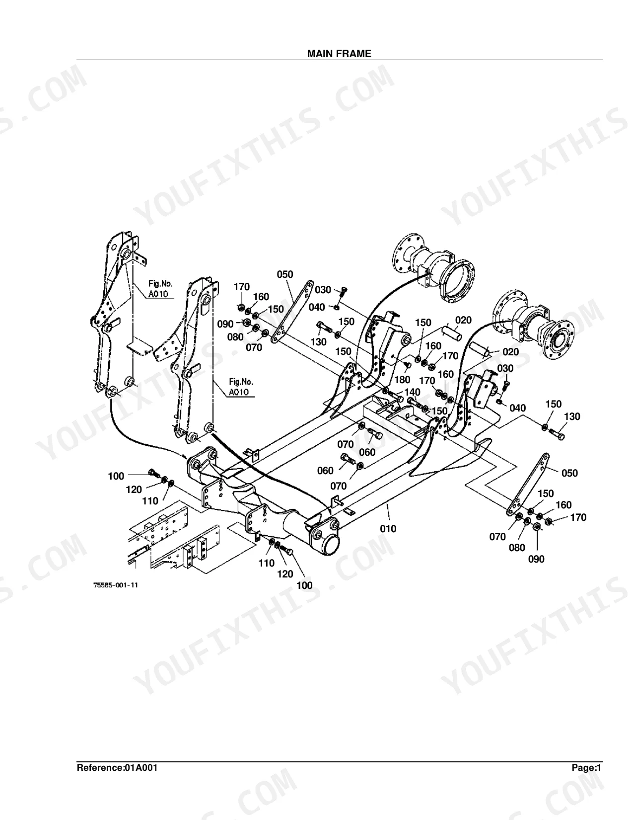
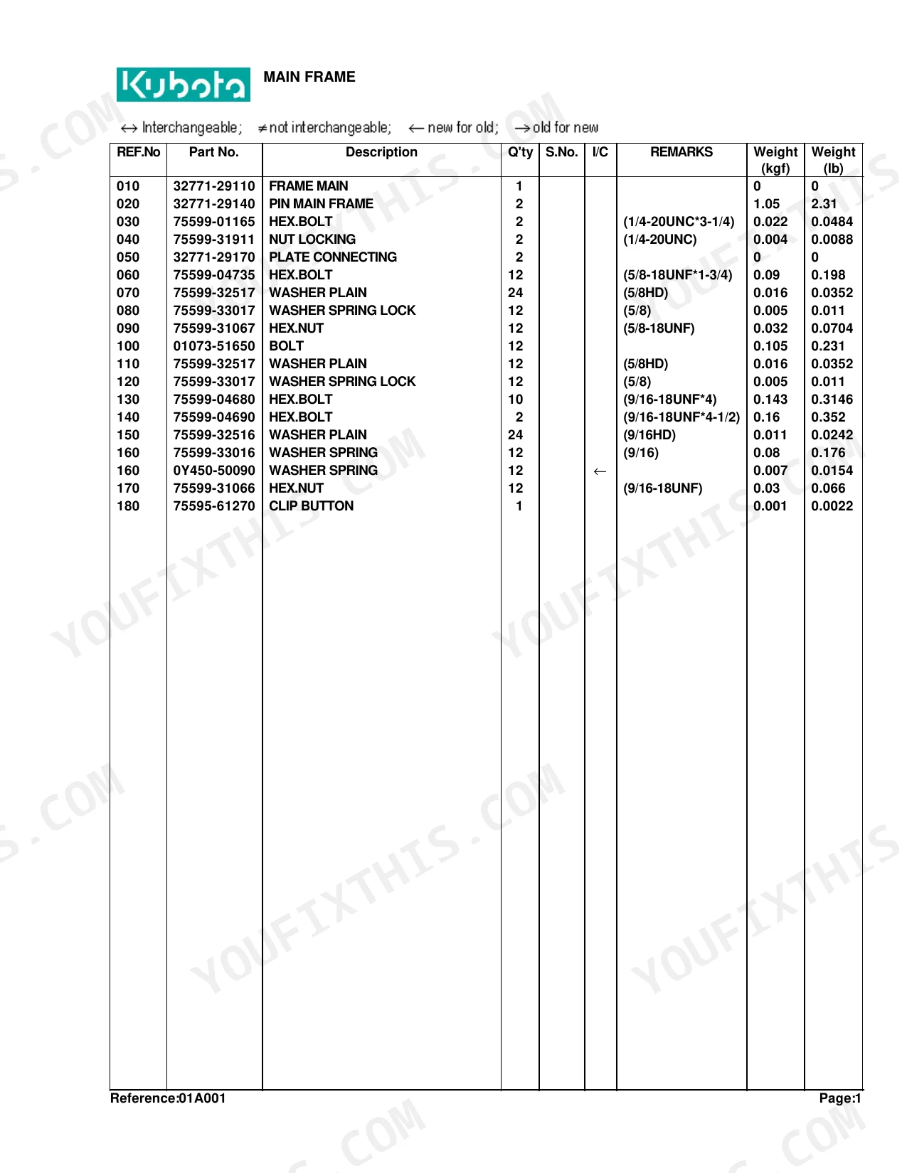
| Main Frame | 4-5 | Frame Main, Hex.bolt, Plate Connecting, Hex.nut, Clip Button |
| Side Frame | 6-8 | Frame Side LH, Label Danger English, Label Warning English, Label Caution English, Label Lubricate English, Frame Side RH, Hex.bolt, Connector |
| Front Guard | 9-10 | Guard Front, Stay, Stay LH, Stay RH, Hex.bolt, Hex.nut |
| Cylinder/Hydraulic Hose | 11-14 | Cylinder, Fitting Grease, Band Code, Hose Hydraulic, Sleeve, Tube P.b, Elbow, Tube Pump |
| Hydraulic Tube | 15-16 | Tube Hydraulic, Hex.bolt, Clamp, Washer |
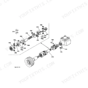
| Boom | 17-18 | Fitting Grease, Label Kubota, Band Code, Label L48, Bushing, Hex.bolt, Comp Link |
| Bucket | 19-20 | Bucket Round, Bucket Squard, Edge Cutting, Label Leveler, Fitting Grease, Hex.bolt, Blade Bolt on Option, Plow Bolt Option |
| Control Valve 1 [Component Parts] | 21-22 | Valve Control, Assy Inlet Section, Assy Spool Section, Clevis End, Spacer-Cap Spool, Plate-Seal, Cap Screw-soc.hd, Cap-Spool |
| Control Valve 2 [Component Parts] | 23-24 | Valve Self Level, Spring, Load Check, Adjustment Cap, Retaining Ring, Relief Valve Assembl |
| Control Valve | 25-26 | Stay Valve, Hex.bolt, Valve Control, Assy Elbow Adjustabl, Assy Plug Orifice, Assy Adapter, Throttle, Assy Elbow Adjusta |
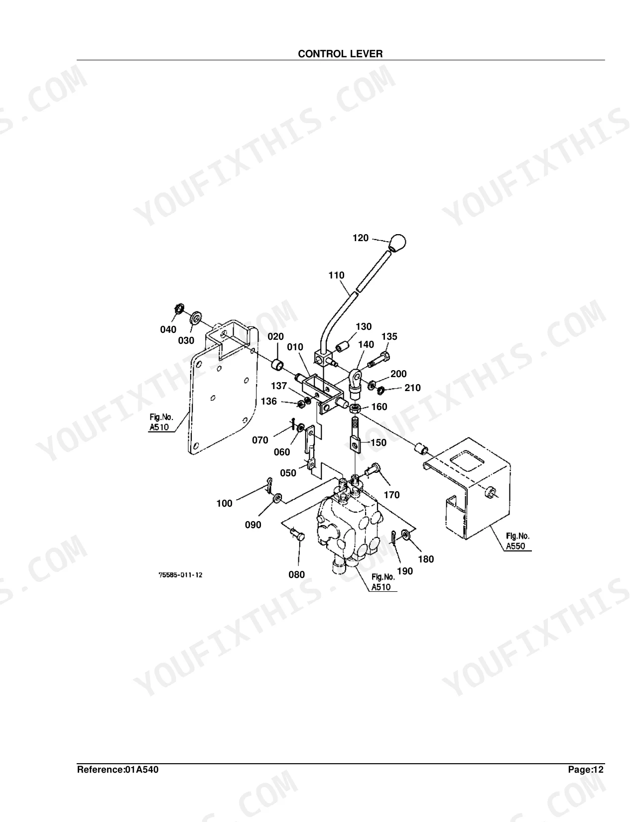
| Control Lever | 27-28 | Lever, Bushing, Collar, Rod, Lever Control, Grip Lever, Sleeve, Hex.bolt |
| Lever Cover | 29-30 | Cover, Bushing, Hex.bolt, Label Control English, Label Control French, Assy Limiter, Hinge, Cushion Rubber |
| Cylinder (Boom) [Component Parts] | 31-32 | Cylinder, Tube, Rod, Head, Piston, Kit Seal, Fitting Grease |
| Cylnder (Bucet) [Component Parts] | 33-34 | Cylinder, Tube, Rod, Head, Piston, Kit Seal, Fitting Grease, Bushing |
| Accessories and Service Parts | 35-36 | Operator S Manual English, Operator S Manual French |
Quick Reference Specifications
| Specification | Value | Page |
|---|---|---|
| Main Frame Hex Bolt (030) Thread Spec | 1/4-20UNC*3-1/4 | p. 5 |
| Main Frame Hex Bolt (030) Weight | 0.022 kgf | p. 5 |
| Main Frame Nut Locking (040) Thread Spec | 1/4-20UNC | p. 5 |
| Main Frame Nut Locking (040) Weight | 0.004 kgf | p. 5 |
| Front Guard Bolt (030) Dimension | M12*1.25*35 | p. 10 |
| Front Guard Bolt (030) Weight | 0.045 kgf | p. 10 |
| Front Guard Hex Bolt (080) Thread Spec | 9/16-18UNF*2-1/2 | p. 10 |
| Front Guard Hex Bolt (080) Weight | 0.1 kgf | p. 10 |
| Cylinder/Hydraulic Hose Cylinder 1 (010) Weight | 15.5 kgf | p. 12 |
| Cylinder/Hydraulic Hose Fitting Grease (015) Angle | 90DEG. | p. 12 |
| Boom (010) Weight (S.No. >=12529) | 196 kgf | p. 18 |
| Bucket Edge Cutting (015) Weight | 60 kgf | p. 20 |
Kubota TL1150 Common Problems This Manual Covers
Cannot find the correct seal kit part number to rebuild the boom lift cylinder
Inspect the exploded view on page 31 to identify the exact seal kit. Cross-reference the main cylinder assembly on page 12, noting the specific 15.5 kgf weight for Cylinder 1, and order the matching head and piston components.
Manual Section: Cylinder (Boom) [Component Parts] p. 31Front loader bucket cutting edge is heavily worn and requires replacement parts identification
Review the bucket assembly diagram on page 19 to locate the bolt-on blade components. Find the correct part numbers for the Edge Cutting assembly, which weighs exactly 60 kgf according to page 20, then order the matching pins and grease fittings.
Manual Section: Bucket p. 19Missing the correct replacement mounting bolts for the front grille guard after frame repairs
Examine the front guard parts list on page 9 to identify the missing fasteners. Order the exact M12*1.25*35 dimension bolts shown on page 10, verifying you also have the correct hairpin cotters and clevis pins to secure the assembly.
Manual Section: Front Guard p. 9Unable to identify replacement locking nuts and hex bolts for loose chassis connecting plates
Check the chassis parts diagram on page 4 to locate the connecting plate hardware. Use the parts list on page 5 to order the exact 1/4-20UNC locking nuts and 1/4-20UNC*3-1/4 hex bolts required for a secure frame.
Manual Section: Main Frame p. 4Frequently Asked Questions
What are the replacement specifications for hydraulic hoses?
Replacement specifications for hydraulic hoses include the part number and weight. For example, HOSE 8 HYDRAULIC uses part number 75585-66610 and weighs 0.495 kgf (1.089 lb). Other lines, like HOSE 1 HYDRAULIC (Part No. 75585-66110), are listed with their respective weights. p. 12
Where do I find the seal kit part numbers for the Kubota TL1150 boom lift cylinder?
The boom lift cylinder assembly is shown on page 31. Cylinder 1 weighs 15.5 kgf per the parts list on page 12. The exploded view on page 31 breaks out the seal kit, head, and piston components as separate line items so you can order only the seals rather than the full cylinder. p. 31
What does the Kubota TL1150 bucket cutting edge assembly weigh?
The Edge Cutting assembly weighs exactly 60 kgf per page 20. Page 19 diagrams the bolt-on blade components and their matching pins and grease fittings. Use the assembly weight to verify the complete kit arrived before installation. p. 20
What bolt dimensions are required for the Kubota TL1150 front grille guard?
Page 10 lists the required bolts as M12*1.25*35 dimension bolts. The same parts list covers the hairpin cotters and clevis pins needed to secure the front guard assembly. Match all fastener dimensions exactly before ordering. p. 10
What fastener sizes are listed for the Kubota TL1150 chassis connecting plates?
Page 5 lists 1/4-20UNC locking nuts and 1/4-20UNC*3-1/4 hex bolts for the connecting plates. The chassis parts diagram on page 4 shows the exact positions of these fasteners on the main frame. p. 5
What do I get after purchasing this Kubota TL1150 manual?
You receive an instant PDF download immediately after payment. The full 36-page searchable Parts Catalog can be opened on your laptop, tablet, or phone directly in the shop.
Am I able to print pages from this manual?
Yes, you can print as many copies as you want without any restrictions. Many mechanics print the specific section they need and bring it directly to the shop floor.


Reviews
There are no reviews yet.