

Part of the Kubota Parts Manuals.
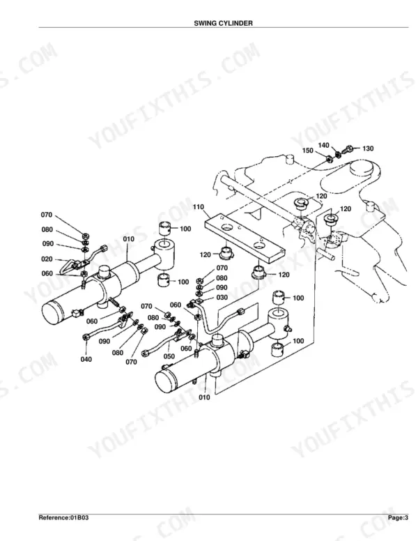
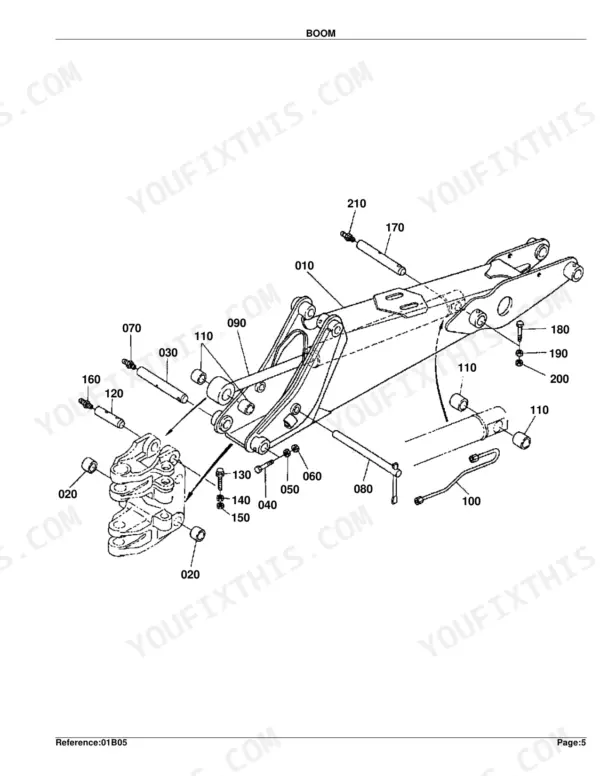
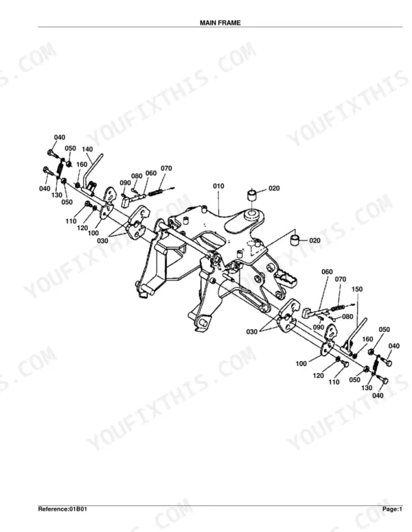
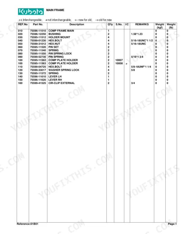
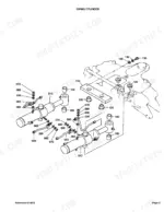
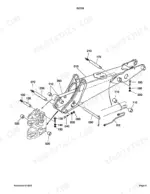
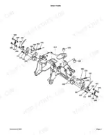
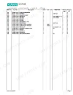
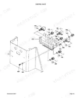
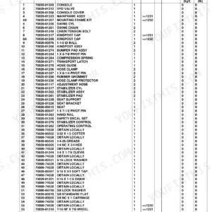
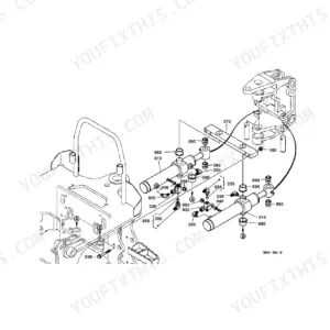
This is the factory parts catalog for the Kubota BT751 backhoe attachment, a 53-page illustrated PDF you can download and print. It breaks the machine down section by section, pairing an exploded diagram of each assembly with its matching parts list, reference numbers, and Kubota part numbers.
Coverage runs across the whole backhoe: main frame and swing frame, the swing, boom, dipperstick, bucket, and stabilizer cylinders and their component parts, the bucket and bucket link, the control valve, and every hydraulic hose group. Each part carries its quantity and serial-number range so you can confirm a number fits your machine before you order.
Use it to identify the exact replacement part from the diagram rather than guessing, cross-check interchangeability between serial ranges, and plan a rebuild of a worn cylinder or linkage. It is a parts reference, not a step-by-step repair manual.
Complete the set for your BT751
- Repair Manual: Kubota B21, TL421, BT751 Shop Manual (incl. Wiring)
What's Inside This Kubota BT751 Parts Manual
| System | Pages | Key Topics |
|---|---|---|
| Hydraulics & 3-Point Hitch | Swing Cylinder, Boom Cylinder, Dipperstick Cylinder, Bucket Cylinder, Stabilizer Cylinder LH, Stabilizer Cylinder RH, Control Valve, Hydraulic Hose | |
| Loader, Backhoe & Attachments | Swing Frame, Boom, Dipperstick, Bucket Link, Bucket, Stabilizer Arm | |
| Body & Operator Station | Main Frame, Step | |
| Decals & Accessories | Label, Accessories and Service Parts | |
| Other Components | Control Lever 1, Control Lever 2 |
Every system also includes interchangeability symbols.
Quick Reference Specifications
| Specification | Value | Page |
|---|---|---|
| Relief Valve Pressure | 2525 PSI | p. 36 |
| Pin (Boom) Dimension | 1.18*8.62 | p. 12 |
| Head (Boom Cylinder) Dimension | 2.75*1.38 | p. 14 |
| Pin (Dipperstick) Dimension | 1.18*7.96 | p. 16 |
| Pin (Bucket Link) Dimension | 0.98*6.68 | p. 20 |
| Pin (Stabilizer Arm) Dimension | 0.98*6.93 | p. 26 |
| Head (Stabilizer Cylinder LH) Dimension | 2.50*1.38 | p. 28 |
Kubota BT751 Common Problems This Manual Covers
Confusion reinstalling the boom cylinder
Owners report trouble getting the boom cylinder oriented correctly when reinstalling it after hose or cylinder work, which leaves the backhoe digging inconsistently. The exploded view and component parts list make the assembly order and fitting positions clear.
Manual Section: Boom Cylinder (Component Parts) p. 13Worn bucket link pins and bushings
Pins and bushings at the bucket link wear over time and introduce slop in the digging linkage. The parts list identifies each replaceable pin and bushing with its dimension and part number.
Manual Section: Bucket Link p. 19Leaking hydraulic hoses and fittings
Aging hoses and loose fittings weep oil and cost the backhoe power. The hose groups are diagrammed so you can trace the inlet and outlet lines and order the correct replacement hose and fitting.
Manual Section: Hydraulic Hose (Inlet/Outlet) p. 37Control valve wear or sticking
A worn or sticking control valve makes the backhoe respond slowly or unevenly. The control valve section lays out the valve and its internal parts for inspection and part identification.
Manual Section: Control Valve p. 33Seized or stiff stabilizer cylinders
Stabilizer cylinders can seize or leak from corroded rods and worn seals, leaving the legs slow to set. The LH and RH stabilizer cylinder breakdowns identify the seals and internal parts you need.
Manual Section: Stabilizer Cylinder Lh (Component Parts) p. 27Swing cylinder oil bypass
Worn swing cylinder seals let the boom drift or swing weakly under load. The swing cylinder diagram and parts list show the cylinder assembly and its rebuildable components.
Manual Section: Swing Cylinder p. 7Frequently Asked Questions
Which machine does this parts catalog cover?
It covers the Kubota BT751 backhoe attachment. The catalog documents the frame, all cylinders, the bucket and linkage, the control valve, and the hydraulic hose groups for that model.
Does it include exploded diagrams and Kubota part numbers?
Yes. Every section pairs an exploded diagram with a parts list that gives the reference number, Kubota part number, quantity, and serial range. The Main Frame section shows the format the whole catalog follows. p. 3
Can I find the hydraulic control valve parts here?
Yes. The Control Valve section diagrams the valve body and its component parts, which is where you confirm the exact replacement part number if the valve is worn or sticking. p. 33
How do I identify the right pin or bushing?
Match the worn part to its reference number on the exploded diagram, then read across the parts list for the Kubota part number and dimension. The Bucket Link section is a good example of this layout. p. 19
Is this Kubota BT 751 Parts Catalog a digital download?
This is a 53-page searchable PDF, delivered instantly after checkout. Open it on a laptop, tablet, or phone and bring it straight to the shop floor.
Can I print pages of this manual for my own shop?
Yes. Many mechanics print the section they need for their own shop and bring it to the bench.
Can I find hydraulic circuit diagrams in this Kubota BT 751 manual?
Not included. This Kubota BT 751 manual does not contain hydraulic circuit diagrams or schematics. It provides exploded parts views with part numbers, so hydraulic hoses and control valve components are shown as labeled parts within the assembly diagrams.




Reviews
There are no reviews yet.