


Part of the Kubota Parts Manuals.
Order the right part the first time. This Kubota L4400DT parts catalog runs to 315 pages of exploded views, with crankcase, injection pump, rear differential, steering cylinder, and 3-point linkage each broken down into a full parts list of reference numbers, quantities, and interchange codes. The drivetrain gets thirty pages on its own, covering the main shaft, countershaft, PTO clutch, and all three range-shift fork assemblies separately. Need the battery? It's the 80D26R. Checking a circuit? Fuse ratings run from 5A to 40A, listed by position. Replacing a headlight? Both old-type and new-type bulb numbers are spelled out. A wrong part means another round of shipping and downtime, so the catalog is bookmarked and keyword-searchable: pick the system, find the number, place the order.
What's Inside This Kubota L4400DT Parts Manual
| System | Pages | Key Topics |
|---|---|---|
| Fuel System | Fuel Camshaft, Engine Stop Lever, Injection Pump, Governor, Speed Control Plate, Nozzle Holder and Glow Plug, Nozzle Holder, Air Cleaner, Accelerator Lever, Accelerator Linkage, Fuel Tank, Fuel Pipe and Fuel Filter, Fuel Filter | |
| Cooling System | Water Flange and Thermostat, Water Pump, Fan, Water Pipe, Radiator, Reserve Tank | |
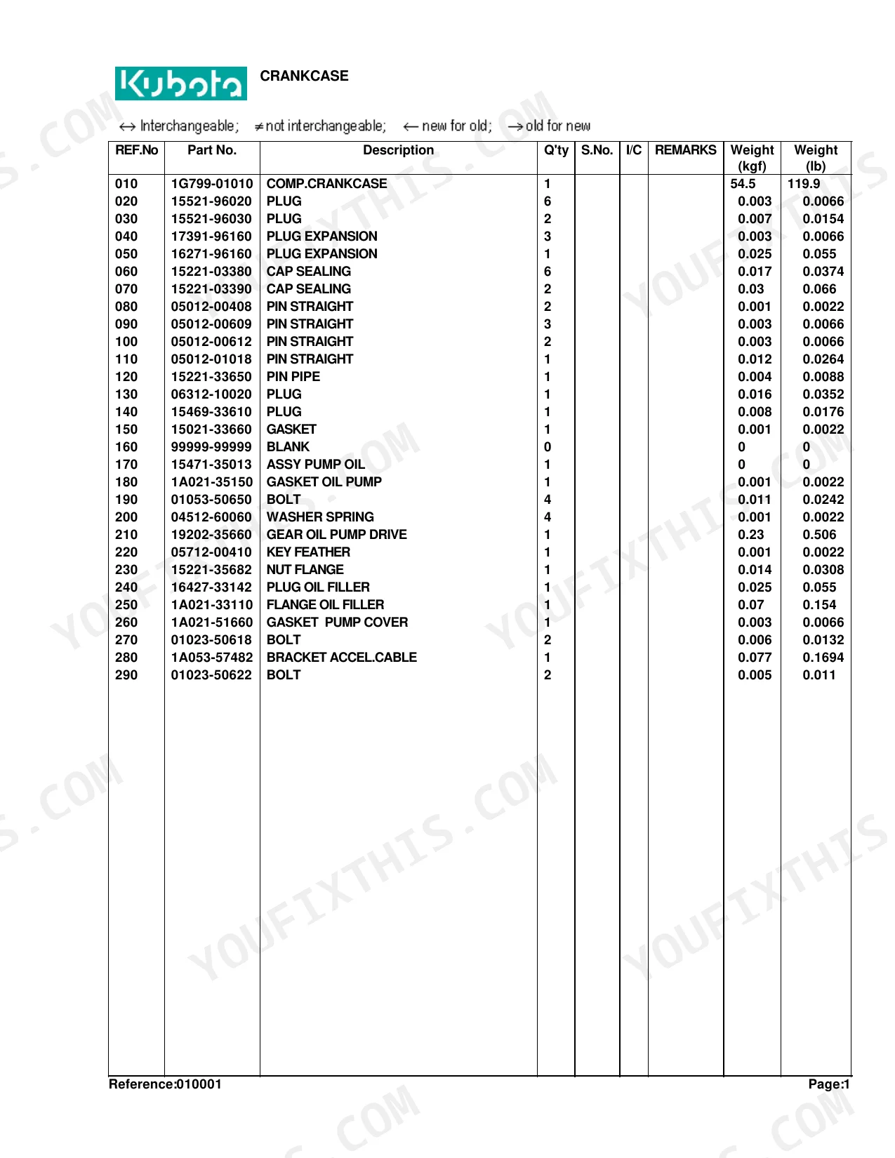
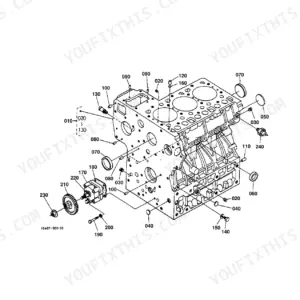
| Engine | Crankcase, Oil Pan, Cylinder Head, Gear Case, Main Bearing Case, Camshaft and Idle Gear Shaft, Piston and Crankshaft, Flywheel, Valve and Rocker Arm, Inlet Manifold, Exhaust Manifold/Muffler, Upper Gasket Kit, Lower Gasket Kit | |
| Electrical System | Alternator, Starter, Battery, Switch 1 / Relay, Switch 2 / Sensor, Panel Board, Head Light, Hazard Light, Rear Lamp, Electrical Wiring | |
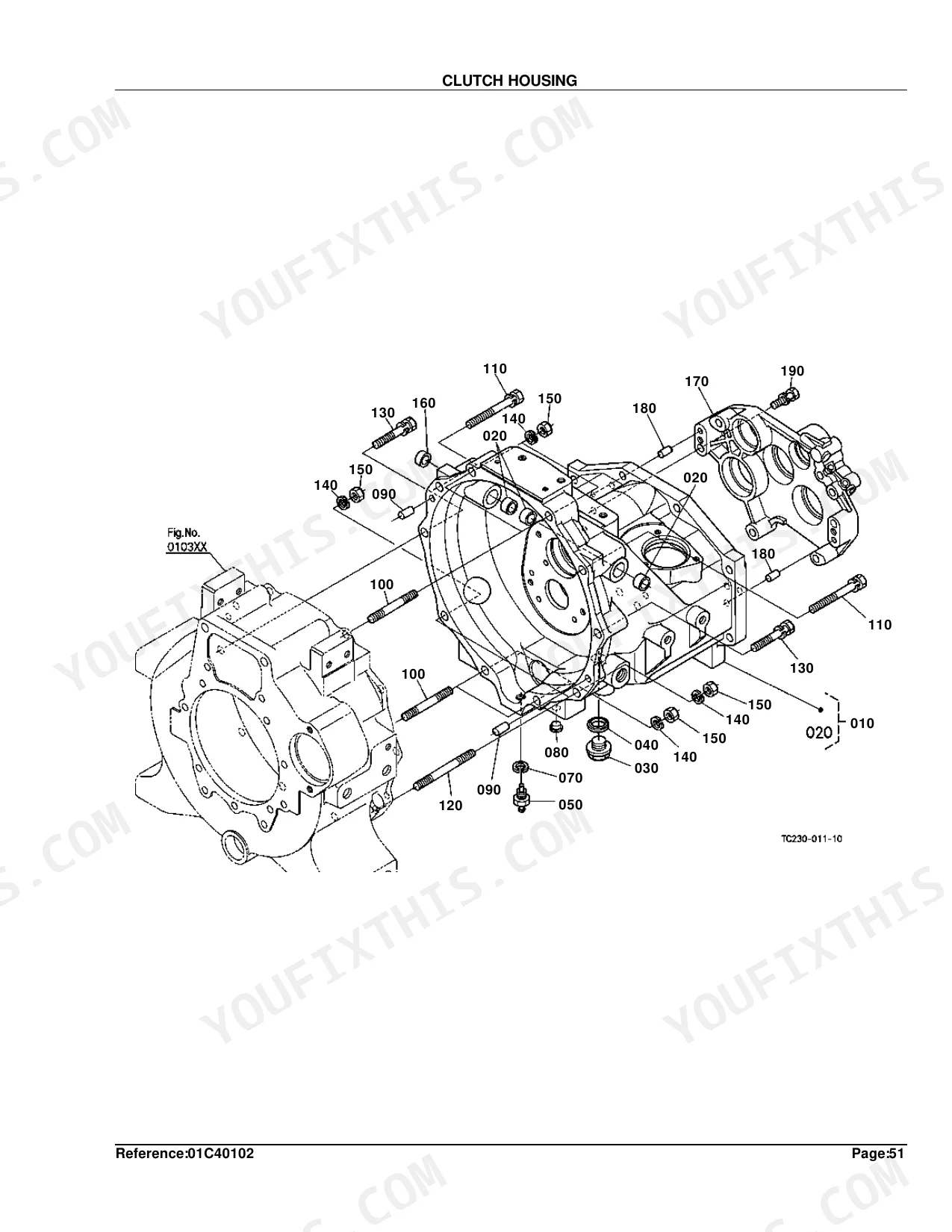
| Clutch & Transmission | Clutch, Clutch Lever, Clutch Pedal, Clutch Housing, Mid Case, Transmission Case, Main Shaft, Countershaft, Range Gear Shaft, PTO Countershaft, PTO Clutch, Main Gear Shift Fork, Range Gear Shift Fork, Differential Lock Shift Fork, Main Gear Shift Lever, Range Gear Shift Lever | |
| PTO | PTO Shaft, PTO Hydraulic Oil Line, PTO Protector | |
| Rear Axle, Differential & Brakes | Rear Differential, Rear Axle LH, Rear Axle RH, Brake LH, Brake RH, Brake Rod 1, Brake Rod 2, Brake Pedal, Rear Wheel | |
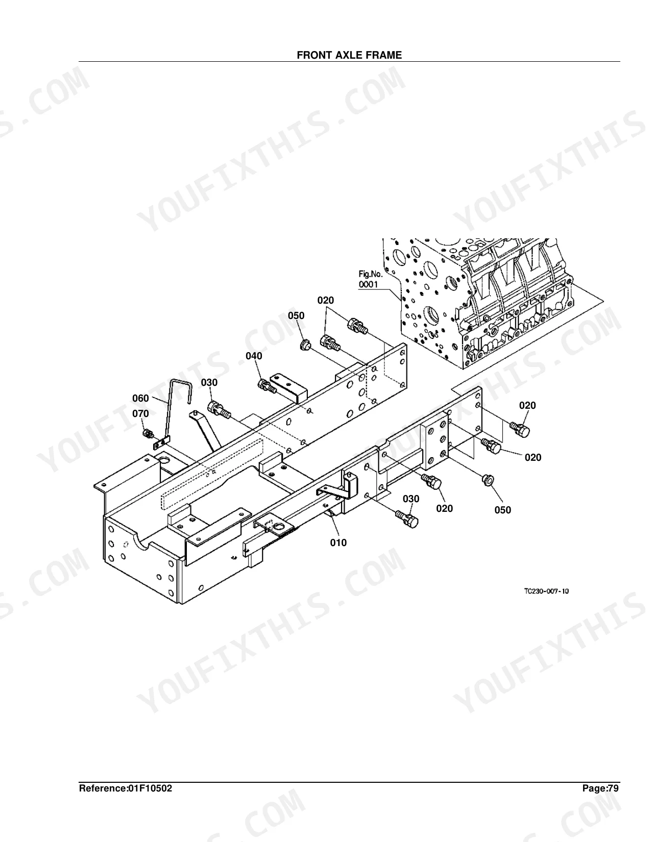
| Front Axle & Steering | Spiral Bevel Pinion, Front Wheel Drive Lever, Front Axle Frame, Propeller Shaft, Front Wheel Drive Shaft, Front Differential Case, Front Axle Case LH, Front Axle Case RH, Differential Gear Shaft, Front Axle, Steering Handle, Steering Controller, Steering Support, Steering Cylinder, Front Wheel | |
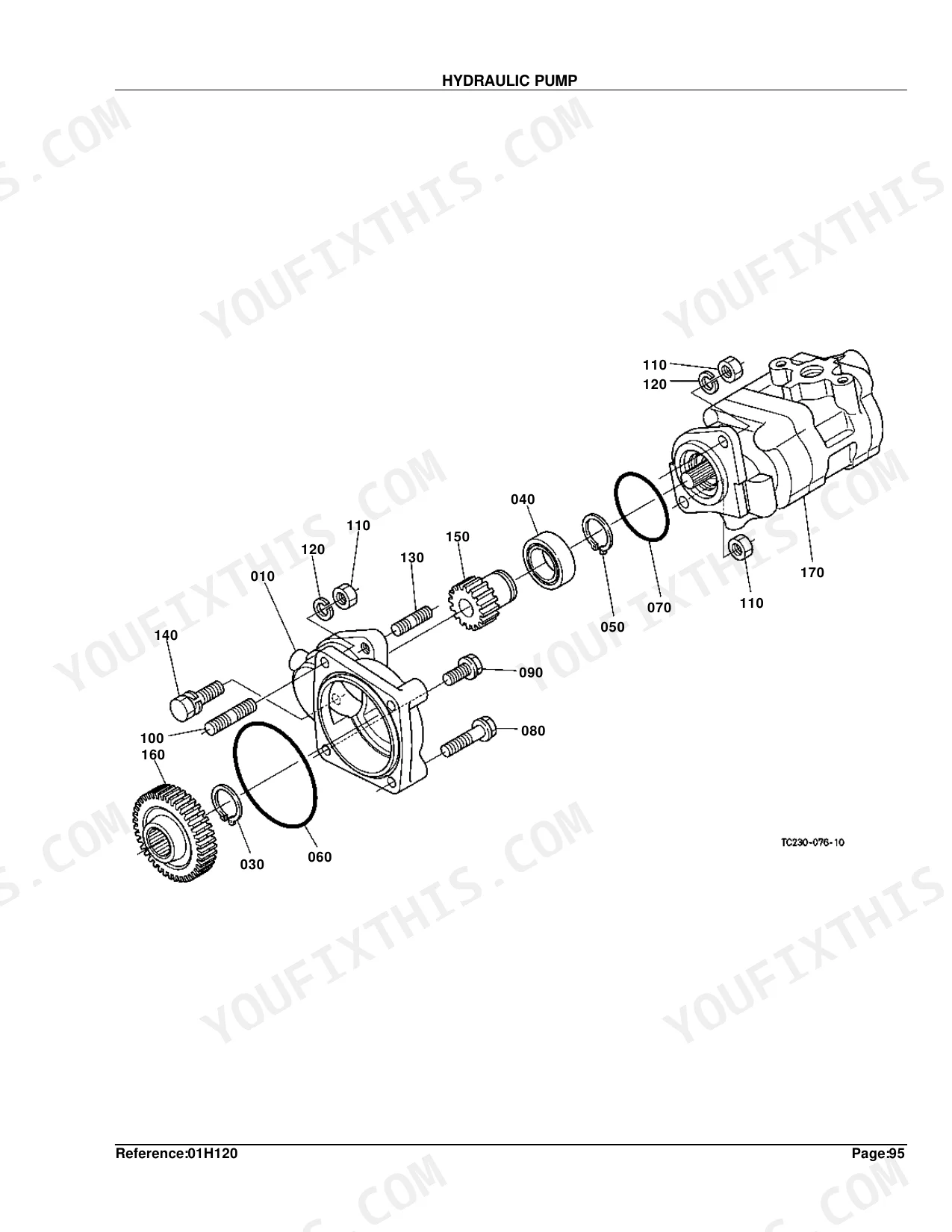
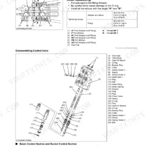
| Hydraulics & 3-Point Hitch | Hydraulic Pump, Regulator Valve, Hydraulic Oil Line, Hydraulic Outlet Block, Hydraulic Cylinder, Lift Arm, Feed Back Lever, Control Valve, Position Control Lever, Top Link, Point Linkage 1, Point Linkage 2, Drawbar, Draft Control Lever, Top Link Holder, Auxiliary Control Valve Lever | |
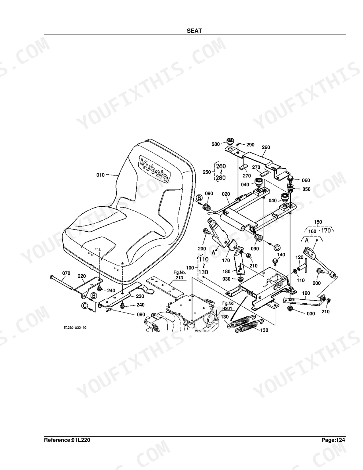
| Body & Operator Station | Head Cover, Front Grille, Hood Front Support, Hood, Hood Side, Hood Side Cover, Shutter Plate, Hood Rear, Fender, Fender Support, Floor Seat Cover / Fender Bracket, Step, ROPS | |
| Decals & Accessories | Tool Box, Label 1, Label 2, Accessories and Service Parts | |
| Other Components | Bevel Gear, Differential, Smv Emblem, Front Bumper, Front Weight |
Quick Reference Specifications
| Specification | Value | Page |
|---|---|---|
| FUSE rating | 5A | p. 101 |
| BATTERY type | 80D26R | p. 83 |
| ASSY BULB power | 1.7W | p. 91 |
| BULB power | 25W | p. 93 |
| BULB LIGHT power | 27W | p. 97 |
| COMP.CRANKCASE Weight | 54.5 kgf | p. 8 |
| COMP.CYLINDER HEAD Weight | 20 kgf | p. 12 |
| CARTRIDGE OIL FILTER Weight | 0.54 kgf | p. 14 |
| COMP.CRANKSHAFT Weight | 16.5 kgf | p. 22 |
| SHIM INJECTION PUMP Thickness | 0.20mm | p. 30 |
| ASSY ALTERNATOR Weight | 3.05 kgf | p. 75 |
| ASSY STARTER Weight | 4.05 kgf | p. 79 |
Kubota L4400DT Common Problems This Manual Covers
Intermittent no-crank, or the engine turns over slowly on cold mornings.
Inspect the starter assembly in the exploded view on page 78. Check that any replacement matches the 4.05 kgf spec, then cross-reference the starter relay and safety switch part numbers before ordering.
Manual Section: Starter p. 78Tractor experiences difficult gear engagement or noticeable clutch slip under heavy loads.
Check the main shaft diagram on page 114 to spot worn transmission parts. Count the main gear shaft teeth against the 22-18-13-10T spec before you order, then pull the part numbers for the clutch release bearing and shift forks.
Manual Section: Main Shaft p. 114Headlights and dashboard warning lights stop working or blow fuses repeatedly during operation.
Open the electrical parts diagram on page 100 to identify the lighting components. Match the 5A fuses called out for the panel board, then locate the part numbers for the harness sections and relays you need to replace.
Manual Section: Electrical Wiring p. 100White smoke from exhaust and loss of coolant pressure indicating a blown head gasket.
Find the head gasket and surrounding internal parts in the page 11 diagram. The complete cylinder head assembly weighs 20 kgf, worth knowing for lifting and handling. Match the valve and rocker arm part numbers to your engine block model.
Manual Section: Cylinder Head p. 11Frequently Asked Questions
What are the replacement specifications for clutch?
Clutch components come with listed replacement weights. The ASSY PLATE PRESSURE (Part No. TA020-20600) is 6.5 kgf (14.3 lb), and the COMP.DISK CLUTCH (Part No. TD020-20500) is 1.03 kgf (2.266 lb). p. 103
What are the replacement specifications for transmission components?
Transmission parts are listed with their replacement data. The CASE TRANSMISSION (Part No. TC230-20400) shows a quantity of 1, while the STUD (Part No. 01574-61260) weighs 0.05 kgf (0.11 lb) and the BOLT (Part No. 01133-51260) weighs 0.06 kgf (0.132 lb). p. 113
Is this Kubota L4400DT Parts Catalog a digital download?
Yes. It's a 315-page searchable PDF you can download right away. It opens on any device, so you can pull it up on your phone while you're under the hood. No shipping, no waiting.
Can I print specific sections of this Kubota L4400DT Parts Catalog?
No restrictions at all. Print individual pages, full chapters, or the entire manual. The PDF is completely unlocked.


Reviews
There are no reviews yet.