


Part of the Kubota Parts Manuals.
This is the factory parts catalog for the Kubota B5200D compact diesel tractor, delivered as a downloadable PDF. It documents the machine group by group across the engine, transmission, clutch, brakes, steering, hydraulics, electrical system, fuel system, and the front axle and front wheel groups for the two and four wheel drive versions.Each group pairs an exploded diagram with a parts table listing reference numbers, Kubota part numbers, quantities, serial number ranges, and interchangeability notes, so you can identify the exact part your tractor needs and confirm it fits your serial number before you order.Use it to source the right filters, seals, clutch and brake parts, or electrical components with genuine Kubota numbers, and to work through an engine, driveline, or hydraulic job on your B5200D without guessing which version of a part to buy.
What's Inside This Kubota B5200D Parts Manual
| System | Pages | Key Topics |
|---|---|---|
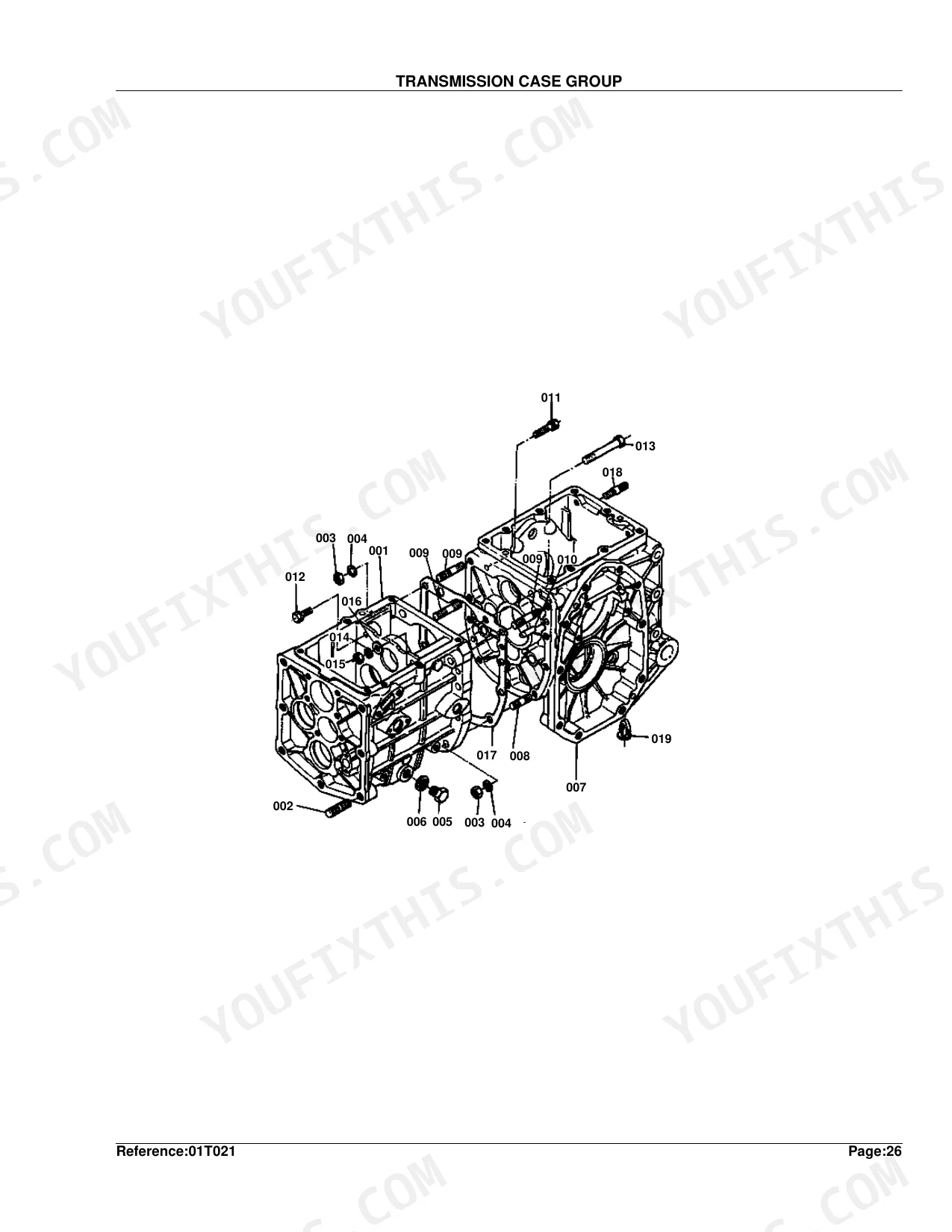
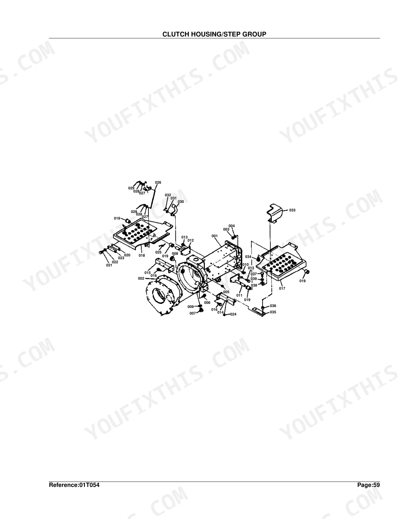
| Clutch & Transmission | Aux.Speed Change, Clutch Rod, Clutch, Clutch Housing/Step, Main Speed Change, Reverse Shaft, Rotary Speed Change Fork, Speed Change Fork, Speed Change Lever, Transmission Case, 2nd Shaft, 3rd Shaft, 4th Shaft/5th Shaft | |
| Fuel System | Decompress Wire and Engine Stop Wire, Engine Stop Lever, Fuel Camshaft, Fuel Tank, Fuel Pipe, Fuel Filter, Governor, Injection Pump, Nozzle Holder, Speed Control Plate | |
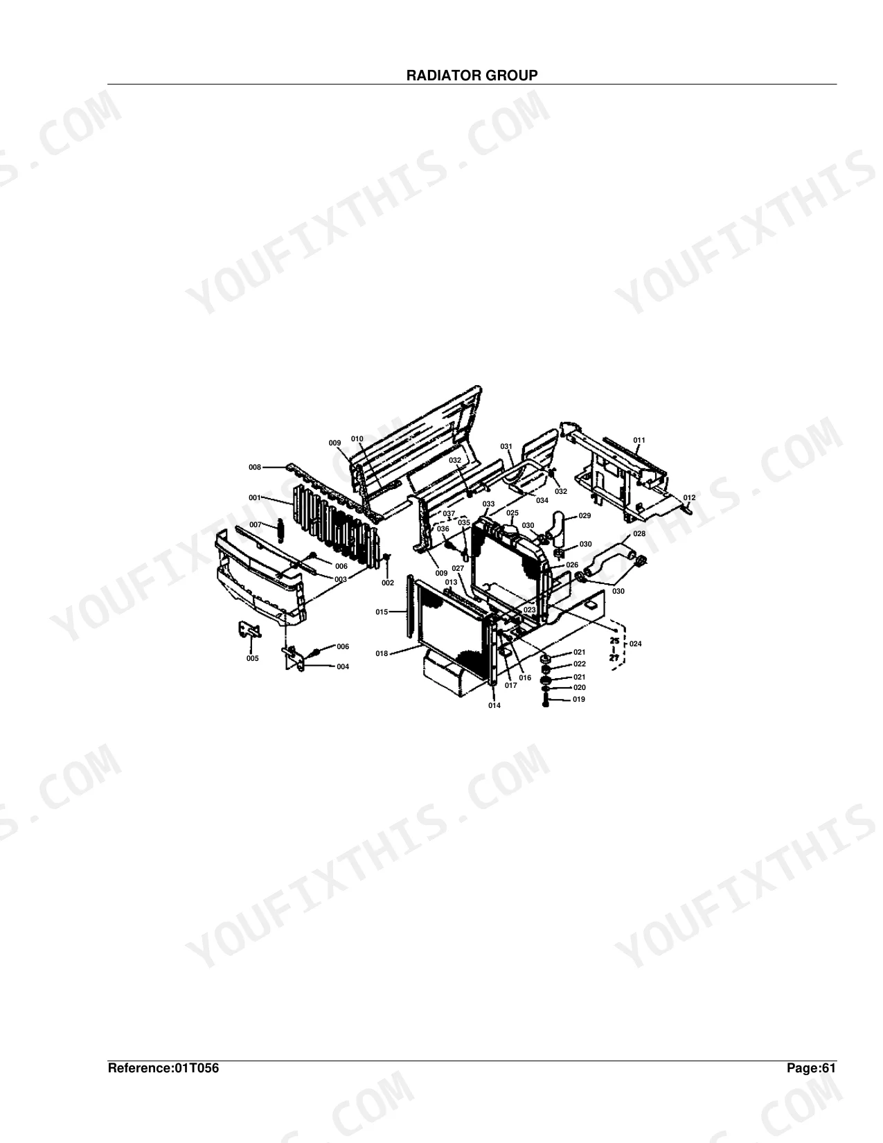
| Cooling System | Radiator, Water Flange, Water Pump | |
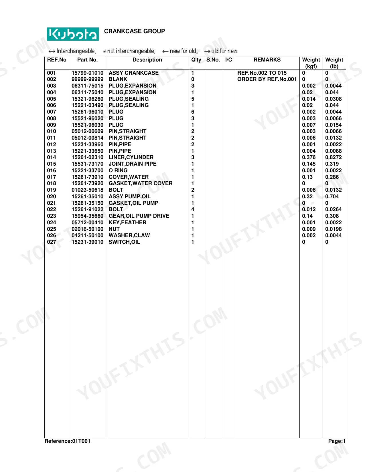
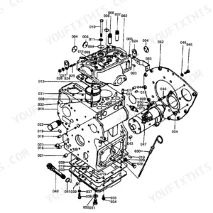
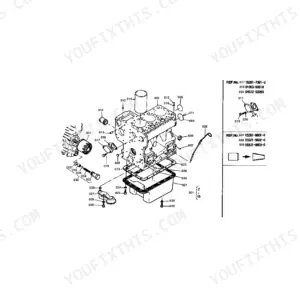
| Engine | Bearing Holder, Crankcase, Cylinder Head, Cylinder Head Cover, Camshaft, Flywheel, Front Wheel Gear Case, Gear Case, Inlet Manifold Exhaust Manifold, Main Bearing Case, Muffler and Muffler Pipe, Oil Pan, Piston/Crankshaft, Valve/Rocker Arm | |
| Electrical System | Battery, Dynamo/Starter, Dynamo, Flasher Lamp, Panel Switch, Starter, Working Light | |
| PTO | PTO Shaft | |
| Rear Axle, Differential & Brakes | Axle Case, Brake, Brake Rod, Front Axle Case, Rear Differential, Rear Axle, Rear Wheel, Spiral Bevel Shaft | |
| Front Axle & Steering | Front Axle Frame, Front Wheel, Front Differential, Front Wheel Hub, Knuckle Arm, Steering | |
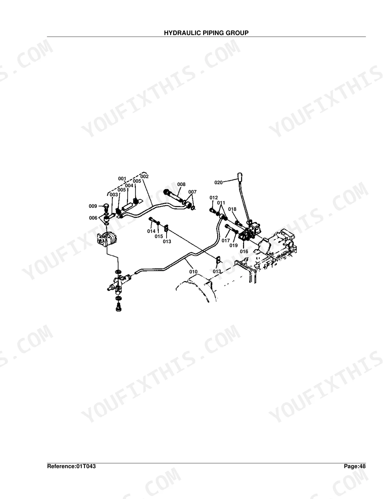
| Hydraulics & 3-Point Hitch | 3-Point Linkage, Control Valve, Gear Pump, Hydraulic Piping, Hydraulic Block, Hydraulic 1, Hydraulic 2, Position Control Valve | |
| Body & Operator Station | Case Cover, Fender, Hood, Panel, Seat | |
| Decals & Accessories | Accessories and Service Parts, Name Plate | |
| Other Components | Drive Shaft, Pedal, Release Lever |
Quick Reference Specifications
| Specification | Value | Page |
|---|---|---|
| Cylinder Liner Weight | 0.376 kgf | p. 28 |
| Oil Pan Weight | 1.1 kgf | p. 8 |
| Rear Axle Weight | 4.64 kgf | p. 74 |
| Clutch Housing Weight (S.No. >=62624) | 16 kgf | p. 112 |
Kubota B5200D Common Problems This Manual Covers
Engine will not shut off
Owners report the B5200D kill circuit failing to stop the engine, forcing them to stall it. The Decompress Wire and Engine Stop Wire Group section shows the stop wire and linkage parts to repair the shutoff.
Manual Section: Decompress Wire and Engine Stop Wire GroupHard starting and fuel trouble
Contaminated fuel or a clogged filter causes hard starts and rough running on this diesel. The Fuel Filter Group section identifies the filters and fuel parts to renew.
Manual Section: Fuel Filter GroupWeak three point hydraulics
Low fluid or worn pump and valve parts leave the hitch slow or unable to hold an implement. The Hydraulic 1 Group section covers the hydraulic components for this system.
Manual Section: Hydraulic 1 GroupClutch slip or drag
A worn clutch disc or release parts make the drive unreliable. The Clutch Group section lists the disc, cover, and release bearing for a rebuild.
Manual Section: Clutch GroupWeak or uneven braking
Brake wear and contamination cut stopping power with age. The Brake Group section identifies the brake parts to service.
Manual Section: Brake GroupCharging or starting faults
A worn dynamo or starter leaves the battery flat or the engine slow to crank. The Dynamo/Starter Group section lists the charging and starting components.
Manual Section: Dynamo/Starter GroupFrequently Asked Questions
Which Kubota model does this parts catalog cover?
It covers the Kubota B5200D compact diesel tractor, including the front axle and front wheel groups for the four wheel drive version and the shared engine, transmission, and hydraulic groups.
How do I match a part to my tractor?
Each listing shows a serial number range and interchangeability note. Compare your tractor's serial number to the range to order the correct version of a part, since some components changed during production.
Does it cover the engine stop and kill switch parts?
Yes. The Engine Stop Lever Group and the Decompress Wire and Engine Stop Wire Group show the stop linkage and cable parts, which is where owners look when the key fails to shut the engine off.
Where are the hydraulic parts listed?
The Hydraulic 1 Group and Hydraulic 2 Group cover the hydraulic system, and the control valve section parts list the valve components for the three point hitch.
What do I get after purchasing this Kubota B5200D manual?
You get a 178-page searchable PDF, downloadable right after checkout. It opens on any device, so you can pull it up on your phone while you're under the hood. No shipping, no waiting.
Am I able to print pages from this manual?
Yes - the PDF is DRM-free, so print whatever sections you need for the shop. Standard letter or A4 paper works fine.
Does this Kubota B5200D Parts Catalog cover the hydraulic system?
Yes. It includes exploded parts diagrams with OEM part numbers for the hydraulic lift group, gear pump, and control valve components.


Reviews
There are no reviews yet.