


Part of the Kubota Parts Manuals.
This is the factory parts catalog for the Kubota L2600DT compact diesel tractor, 263 pages covering the complete machine section by section. Every assembly is shown as an exploded diagram paired with a parts list, so you can match each numbered part to its official Kubota part number, quantity, serial-number range, and interchangeability notes before you order.Coverage runs from the crankcase, cylinder head, injection pump, and cooling system through the electrical wiring, clutch, transmission, rear axle, front axle, steering, and hydraulic lift components. Whether you are rebuilding the engine, chasing a starting fault, or sourcing three-point hitch and hydraulic parts, the catalog lets you identify the exact component for your L2600DT and confirm it fits your serial number. Delivered as an instant PDF download you can search on screen or print for the workshop.
What's Inside This Kubota L2600DT Parts Manual
| System | Pages | Key Topics |
|---|---|---|
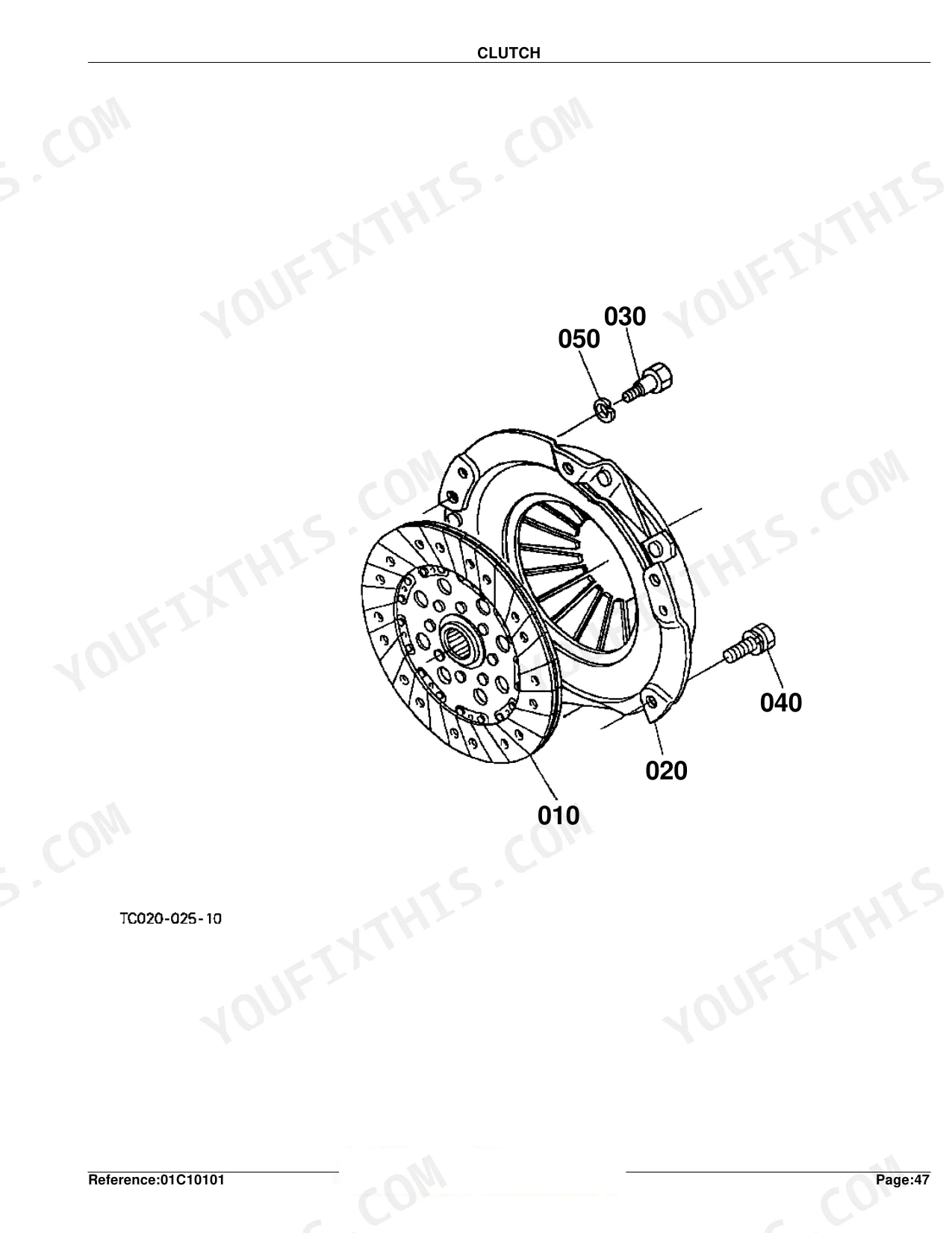
| Clutch & Transmission | Clutch, Clutch Lever, Clutch Pedal, Clutch Housing, Transmission Case, Main Shaft, Countershaft, Reverse Shaft, Range Gear Shaft, PTO Countershaft, Main Gear Shift Fork, Range Gear Shift Fork, PTO Gear Shift Fork, Main Gear Shift Lever, Range Gear Shift Lever, PTO Gear Shift Lever | |
| Fuel System | Fuel Camshaft, Engine Stop Lever, Injection Pump, Governor, Speed Control Plate, Nozzle Holder and Glow Plug, Nozzle Holder, Air Cleaner, Engine Stop Rod, Accelerator Lever, Accelerator Linkage, Fuel Tank, Fuel Pipe and Fuel Filter, Fuel Filter | |
| Cooling System | Water Flange and Thermostat, Water Pump, Fan, Water Pipe, Radiator | |
| Engine | Crankcase, Oil Pan, Cylinder Head, Gear Case, Head Cover, Main Bearing Case, Camshaft and Idle Gear Shaft, Piston and Crankshaft, Flywheel, Valve and Rocker Arm, Inlet Manifold, Exhaust Manifold, Upper Gasket Kit, Lower Gasket Kit, Muffler, Under Muffler | |
| Electrical System | Alternator, Starter, Battery, Switch 1, Switch 2, Panel Board, Light, Electrical Wiring | |
| PTO | PTO Shaft, PTO Protector | |
| Rear Axle, Differential & Brakes | Spiral Bevel Pinion, Rear Differential, Rear Axle, Brake, Hand Brake, Brake Pedal, Front Axle Case, Differential Gear Shaft, Rear Wheel | |
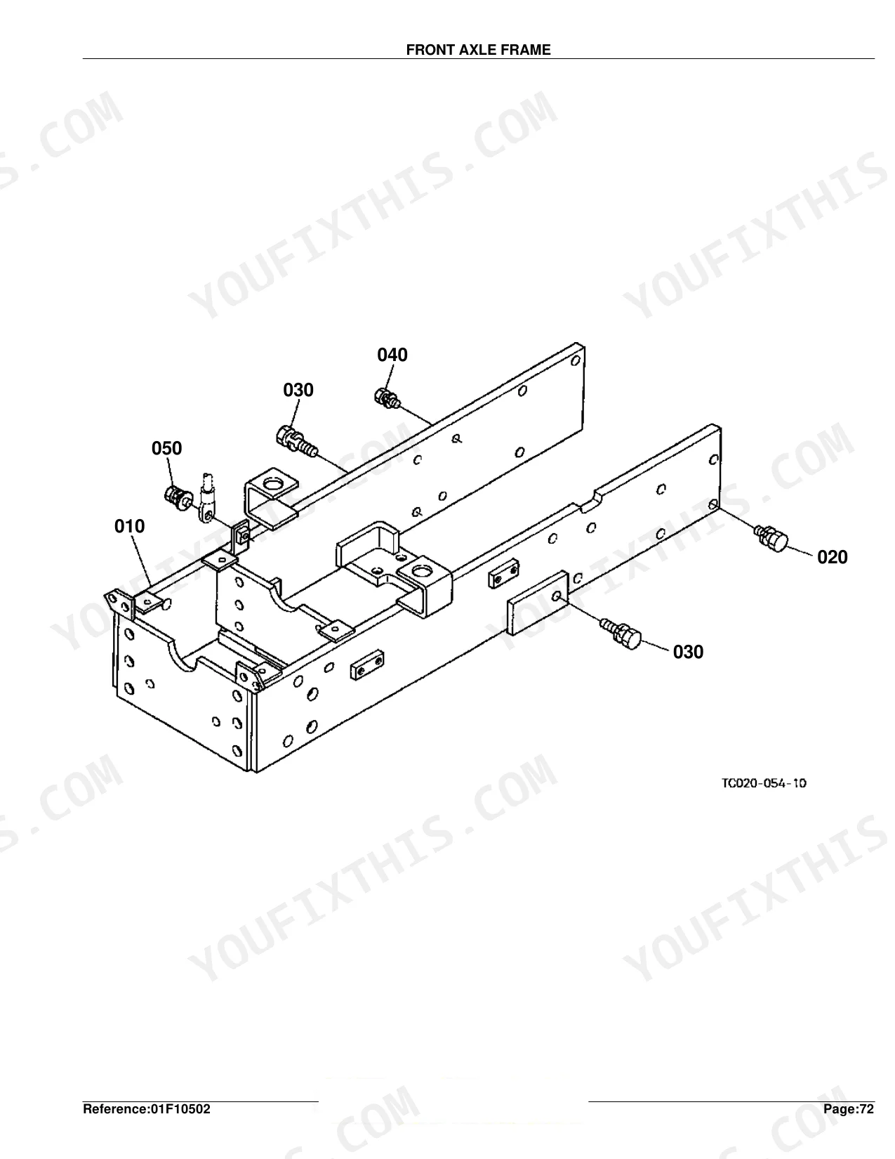
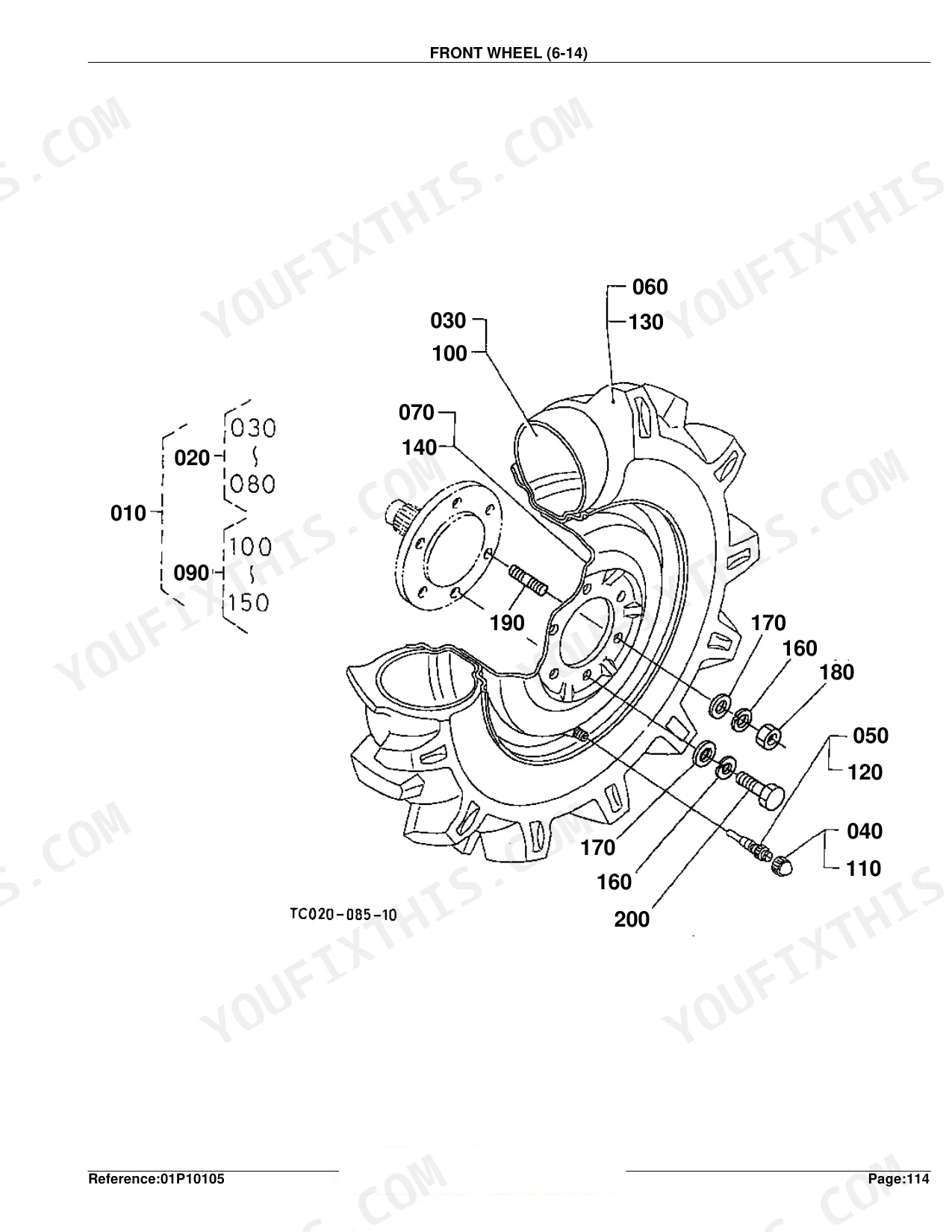
| Front Axle & Steering | Front Wheel Drive Lever, Front Axle Frame, Front Axle Bracket, Propeller Shaft, Front Wheel Drive Shaft, Front Differential Case, Front Differential, Front Axle, Steering Handle, Steering, Steering Linkage, Front Wheel | |
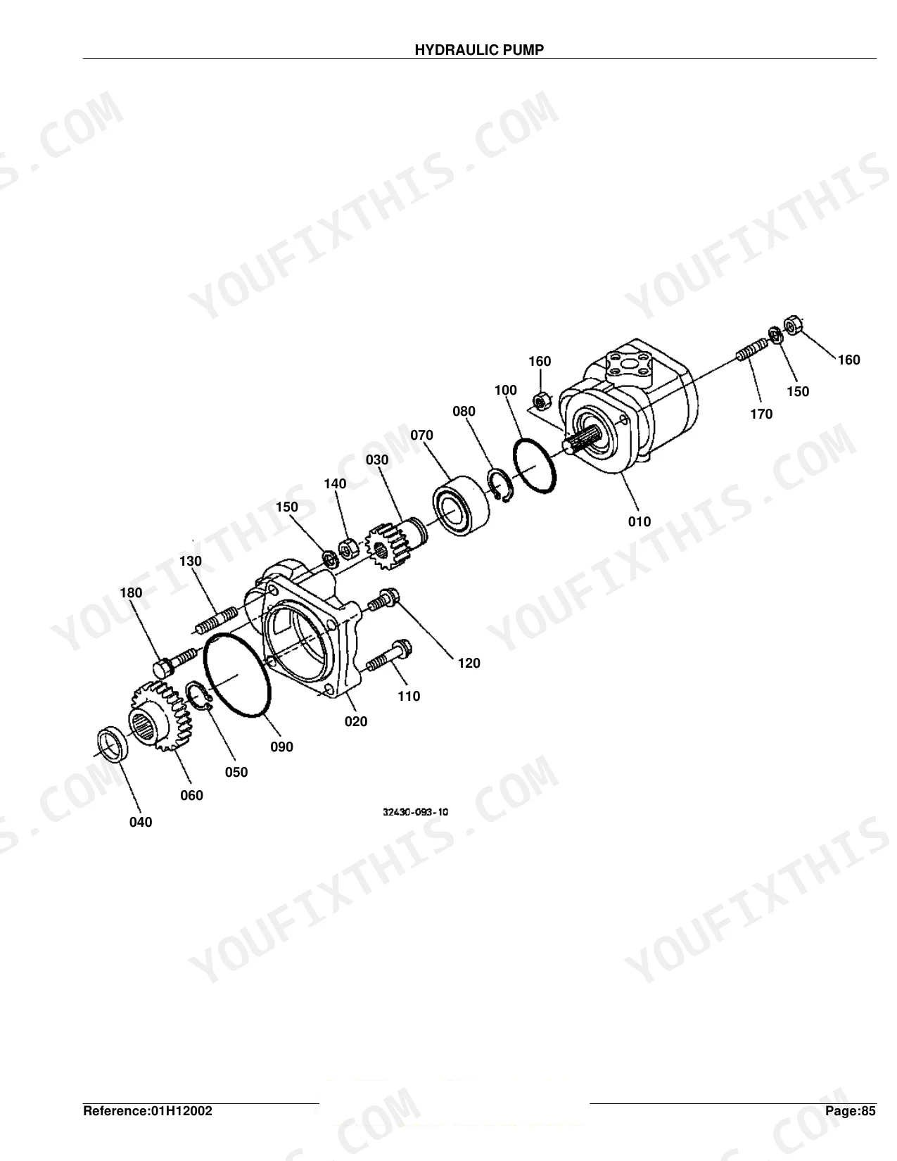
| Hydraulics & 3-Point Hitch | Hydraulic Pump, Hydraulic Oil Line, Hydraulic Cylinder, Cylinder Front Cover, Lift Arm, Feed Back Lever, Control Valve, Position Control Lever, Top Link Holder, Top Link, 3-Point Linkage 1, 3-Point Linkage 2, Drawbar, Draft Control Lever, Draft Control Valve | |
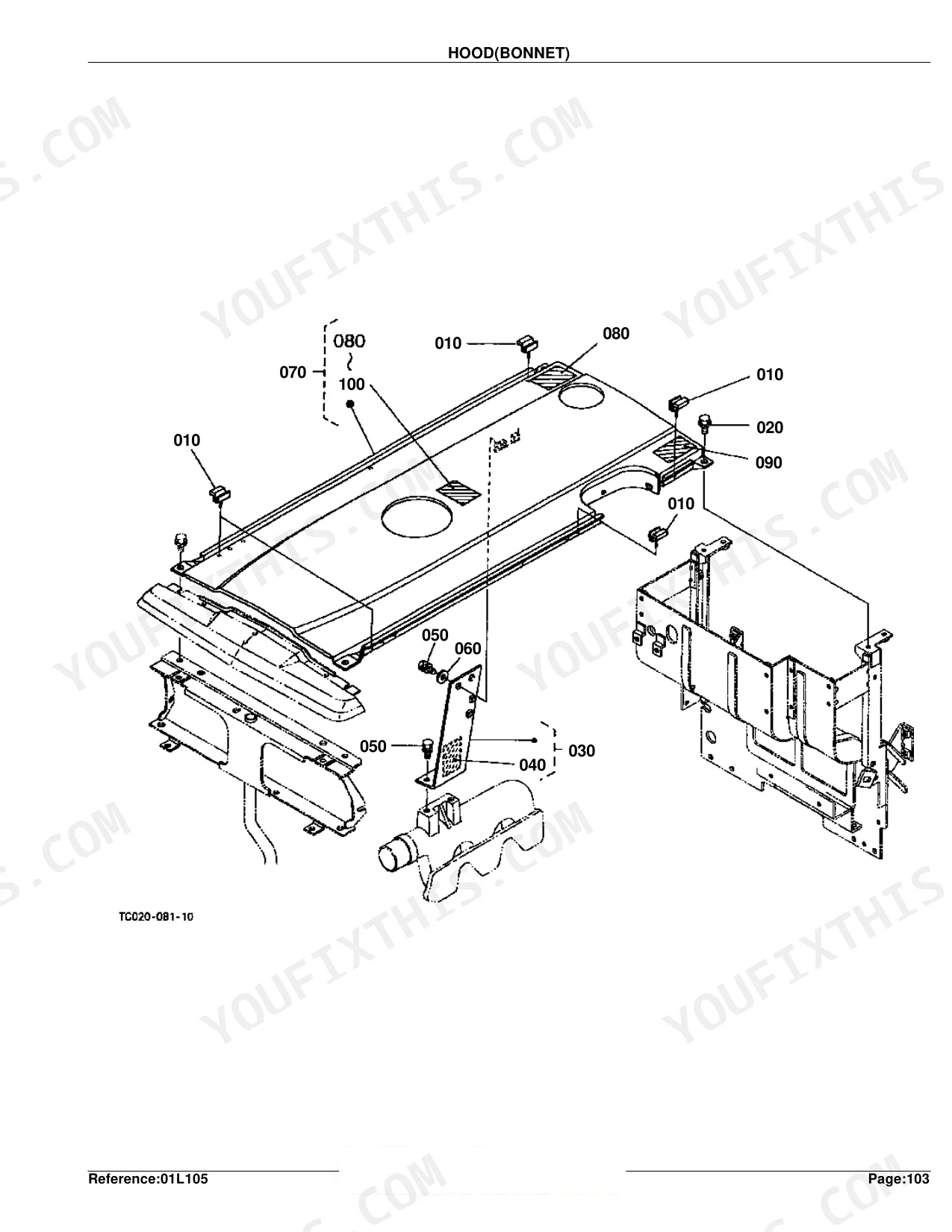
| Body & Operator Station | Front Grille, Hood, Hood Side, Shutter Plate, Panel Frame, Fender, Fender Support, Floor Seat Cover, Seat, Step, ROPS, Smv Emblem | |
| Decals & Accessories | Label 1, Label 2, Accessories and Service Parts | |
| Other Components | Diffrential Lock Pedal |
Every system also includes interchangeability symbols definition.
Quick Reference Specifications
| Specification | Value | Page |
|---|---|---|
| FUSE replacement value | 10A | p. 98 |
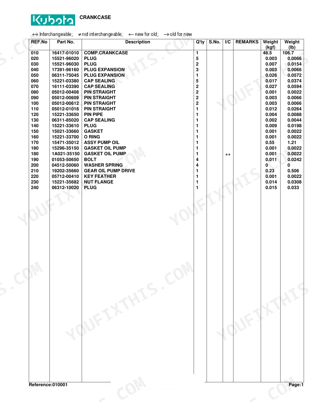
| Complete Crankcase Weight | 48.5 kgf | p. 7 |
| Oil Pan Weight | 2.8 kgf | p. 9 |
| Complete Flywheel Weight | 15.5 kgf | p. 23 |
| Rear Axle Case Weight | 8.8 kgf | p. 132 |
Kubota L2600DT Common Problems This Manual Covers
Engine will not start
A no-start on the L2600DT often comes down to a blown fuse, a bad key switch, the fuel shut-off solenoid, or a corroded wiring connection. This catalog shows every electrical part so you can order the correct fuse or connector, with the panel using 10A and 15A fuses.
Manual Section: Electrical Wiring p. 97Battery not charging
A tractor that runs down its battery or shows a discharged system usually needs alternator or wiring attention. The exploded views let you identify the alternator, its component parts, and the leads to replace.
Manual Section: Alternator p. 77Rough running or air in fuel
Older diesels lose power or stall when the fuel filter clogs or air enters the lines after sitting. Use the parts list to order the correct filter element, gaskets, and fuel lines for a clean bleed.
Manual Section: Fuel Pipe and Fuel Filter p. 67Clutch drag or slip
A worn clutch that will not fully disengage or that slips under load is common on high-hour L2600DT tractors. The clutch section breaks the assembly down so you can match the disc, pressure plate, and release parts.
Manual Section: Clutch p. 99Overheating under load
Overheating usually traces to a blocked radiator, a failing water pump, or a worn fan and belt. The cooling exploded views help you order the correct radiator, pump, and related parts.
Manual Section: Radiator p. 75Weak or dead three-point lift
Lift arms that stop working or lose lift are a frequent L2600DT complaint, often a stuck relief valve or control valve issue. The control valve parts breakdown lets you identify the valve components for repair.
Manual Section: Control ValveFrequently Asked Questions
Which tractor does this parts catalog cover?
It covers the Kubota L2600DT compact diesel tractor. Every section is specific to that model, so the part numbers, serial-number ranges, and interchangeability notes apply directly to your L2600DT.
Does it include exploded diagrams and part numbers?
Yes. All 263 pages are built around exploded diagrams paired with parts lists, giving the reference number, official Kubota part number, quantity, serial-number range, and interchangeability symbol for each component.
What fuses does the electrical system use?
The electrical section lists 10A and 15A fuses for the L2600DT, so you can confirm the correct replacement rating when chasing a no-start or dead-circuit fault. p. 98
Will this help me order hydraulic lift parts?
Yes. The hydraulic sections, including the control valve breakdown, show the lift arm, cylinder, and valve components so you can identify parts when the three-point hitch loses lift.
Is this Kubota L2600DT Parts Catalog a digital download?
Yes. The full 263-page searchable Parts Catalog downloads the moment you buy, and it opens on any device, from your desk laptop to your phone in the field.
Are there any print restrictions on this manual?
Absolutely. No DRM or copy protection. Print the whole manual or just the pages you need. Any home or office printer works.


Reviews
There are no reviews yet.