

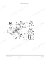
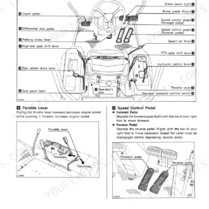

Part of the Kubota Parts Manuals.
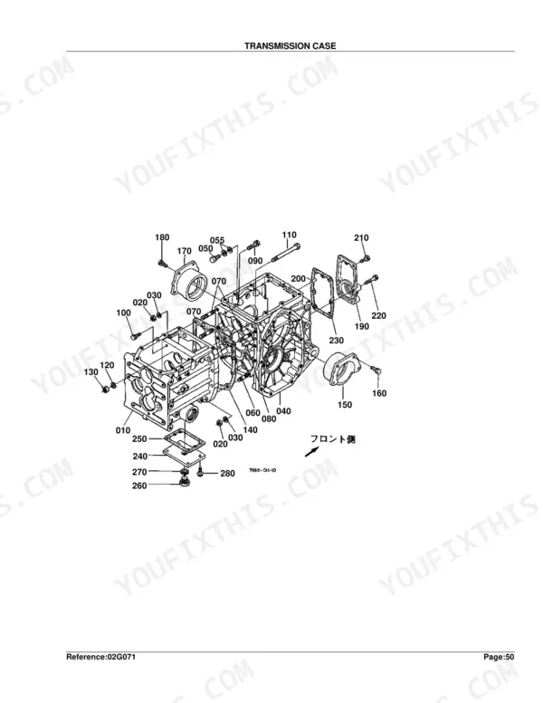
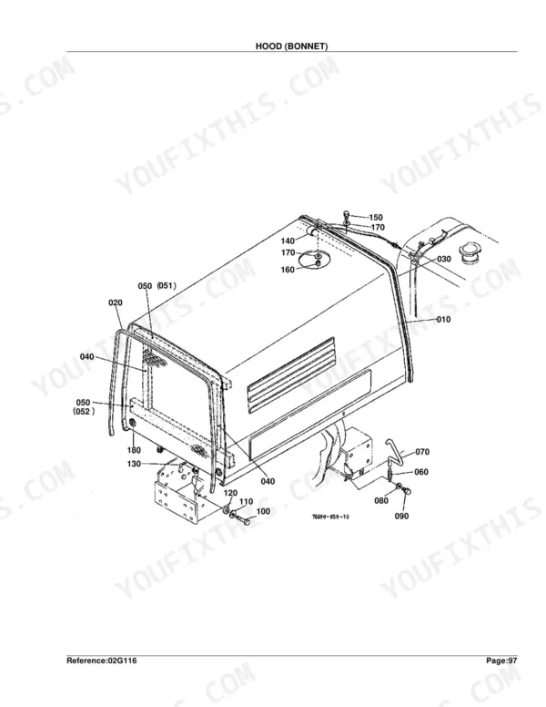
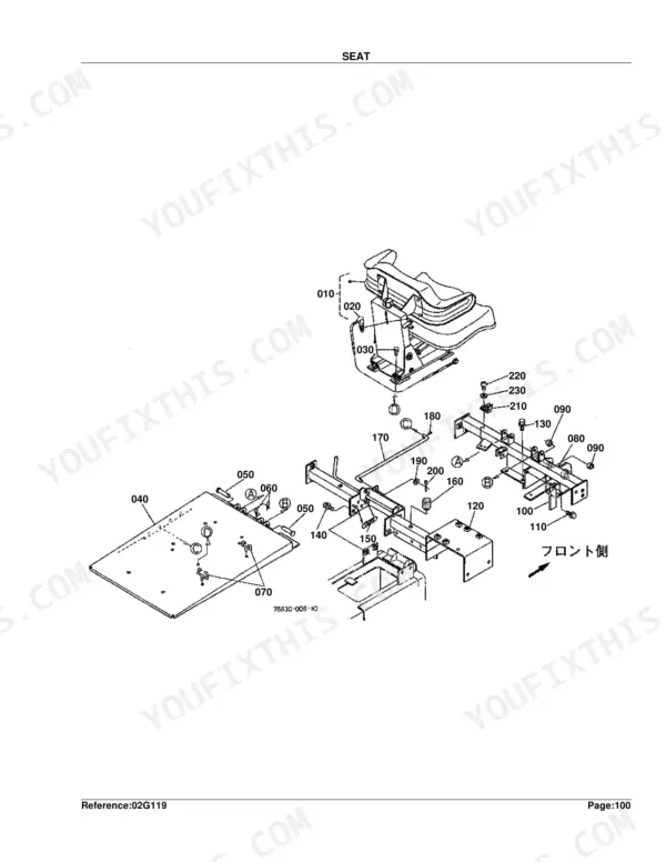
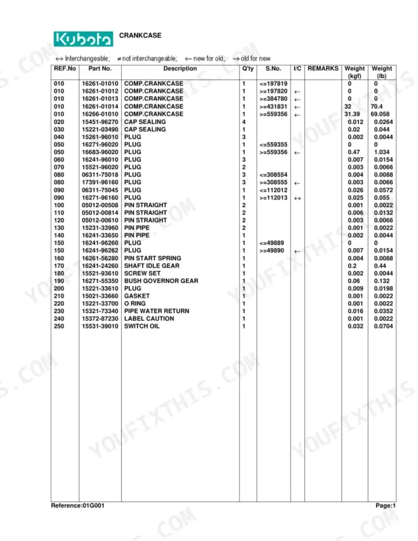
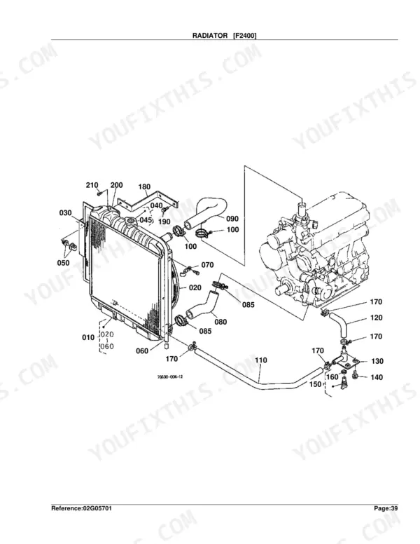
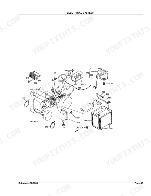
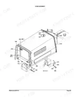
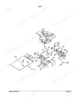
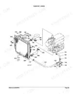
This is the factory parts catalog for the Kubota F2400 and F2100 front mowers, a 243 page illustrated reference that pairs exploded diagrams with the exact part numbers Kubota assigned to each component. Every assembly, from the crankcase and injection pump through the transmission, HST, axles, and hydraulic system, is broken out so you can see how the pieces fit and order the right part the first time.
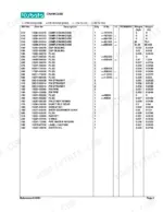
Each parts page lists the reference number, part number, quantity, and the serial number range a part fits, plus the country codes that flag region specific variations. That detail matters on older machines where a component changed partway through production.
Use it to identify worn driveline, clutch, and mower parts, cross check a number before buying, and avoid guessing at subassemblies that are hard to tell apart from the machine alone.
Complete the set for your F2400, F2100
- Repair Manual: Kubota F2400, F2100, F2000 Workshop Manual — Wiring Diagrams
What's Inside This Parts Manual
| System | Pages | Key Topics |
|---|---|---|
| Clutch & Transmission | Clutch, Diff.Lock/Clutch Rod, Clutch Rod, Clutch Housing Frame, Transmission Case, Transmission Case Cover, HST, Speed Change Fork and PTO Lever, Aux.Speed Change and Rear Drive Lever, Speed Change 1, Speed Change 2, Speed Change 3, Mid Case, Universal Joint | |
| Fuel System | Nozzle Holder, Fuel Camshaft, Injection Pump, Engine Stop Lever, Speed Control Plate, Governor, Air Cleaner, Accelerator Lever, Fuel Tank, Fuel Pipe, Fuel Filter | |
| Cooling System | Water Pump, Water Flange, Fan, Radiator, Oil Cooler | |
| Engine | Crankcase, Oil Pan, Piston/Crankshaft, Main Bearing Case, Flywheel, Cylinder Head, Valve/Rocker Arm, Head Cover, Inlet Manifold, Camshaft, Gear Case, Upper Gasket Kit, Lower Gasket Kit, Muffler | |
| Electrical System | Alternator, Starter, Electrical System 1, Electrical System 2, Light Kit | |
| Rear Axle, Differential & Brakes | Axle Case, Brake, Brake Rod, Rear Axle Case, Rear Axle Arm, Rear Wheel, Rear Axle Frame | |
| Front Axle & Steering | Propeller Shaft, Front Axle, Front Wheel, Knuckle Arm, Steering, Power Steering | |
| Hydraulics & 3-Point Hitch | Hydraulic Pump, Power Cylinder, Hydraulic Pipe, Control Valve, Lift Cylinder, Control Valve Kit, Control Valve 2 | |
| Body & Operator Station | Hood, Fender, Front Frame, Seat, ROPS | |
| Decals & Accessories | Label, Accessories and Service Parts | |
| Other Components | Dustproof Plate, Second Shaft, Third/Fifth Shaft, Fourth Shaft, Differential, Pedal, Wheel Hub, Drive Shaft, Handre Post, Link, Link Arm |
Every system also includes a parts list, table title, and figure caption.
Quick Reference Specifications
| Specification | Value | Page |
|---|---|---|
| Piston Ring Oversize | +0.5MM | p. 12 |
| Metal Crankpin Undersize | -0.2MM | p. 12 |
| Metal Crankshaft Undersize | -0.2MM | p. 12 |
| Metal Side Oversize | +0.2MM | p. 12 |
| Nozzle Holder Washer Adjusting Thickness (Min) | 0.900MM | p. 24 |
| Nozzle Holder Washer Adjusting Thickness (Max) | 1.950MM | p. 24 |
| Fuse Rating (Electrical System 1) | 10A | p. 101 |
| Speed Change 2 Shim Thickness (Max) | 1.8MM | p. 143 |
| Differential Shim Thickness (Max) | 1.2MM | p. 153 |
| Differential Side Shim Thickness (Max) | 0.5MM | p. 153 |
| Differential Gear Shaft Shim Thickness (Max) | 0.5MM | p. 153 |


