
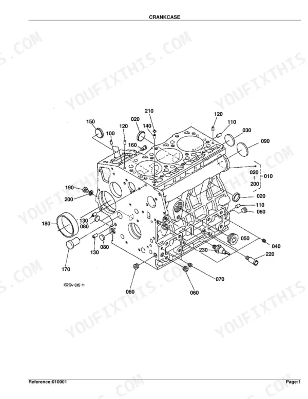
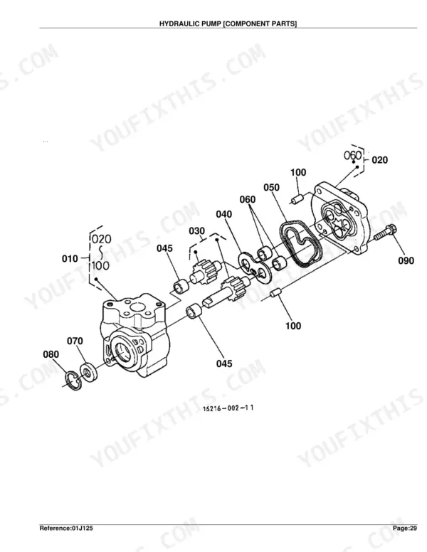
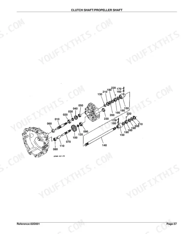
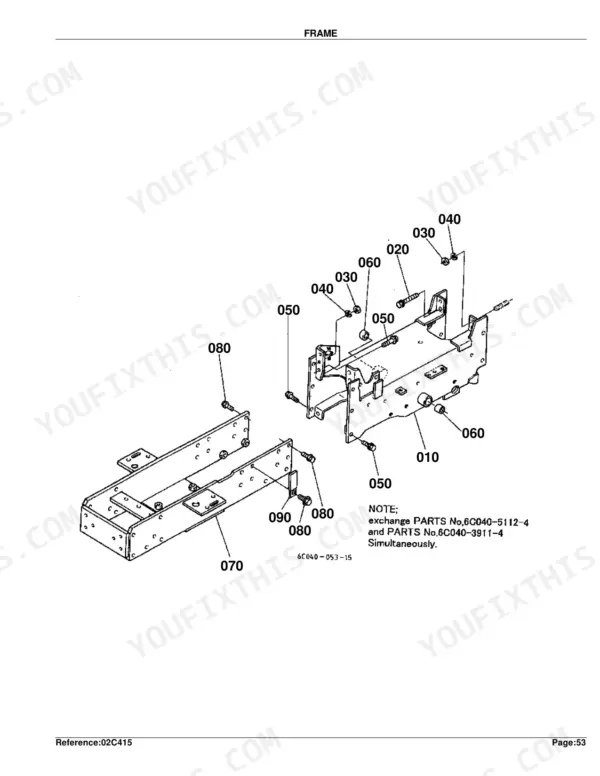
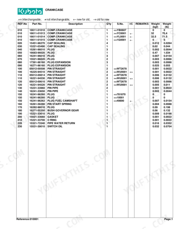
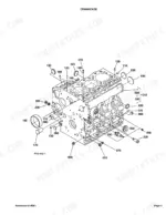
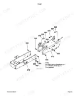
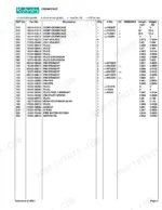
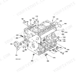
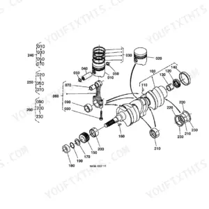
This is the Kubota parts catalog covering the B1700D, B2100D, and B2400D compact diesel tractors, a 261 page illustrated parts book. It documents the machine one assembly at a time: the engine (crankcase, cylinder head, injection pump, governor), the clutch and transmission, front and rear axles, brakes, steering, the hydraulic pump and 3-point hydraulics, cooling, and the electrical system.
Each section is an exploded diagram keyed to Kubota part numbers, quantities, and serial number ranges, with country codes marking parts that vary by market. That lets you pin down the correct component for your exact serial number before buying.
It is the reference for ordering filters, seals, bearings, gaskets, and driveline or hydraulic parts, and for confirming how everything fits together during a rebuild. Delivered as a downloadable, printable PDF for the shop or the field.
Complete the set for your B1700D, B2100D, B2400D
- Repair Manual: Kubota B1700, B2100, B2400 Shop Manual — Wiring Diagrams
What's Inside This Kubota B1700D, B2100D, B2400D Parts Manual
| System | Pages | Key Topics |
|---|---|---|
| Clutch & Transmission | Clutch, Clutch Rod, Clutch Pedal, Clutch Housing, Transmission Case, Clutch Shaft/Propeller Shaft, 2Nd Shaft/3Rd Shaft/4Th Shaft, Main Gear Shift Fork, Main Gear Shift Lever, Range Gear Shift Lever, PTO Gear Shift Lever | |
| Fuel System | Fuel Camshaft and Governor Shaft, Stop Solenoid, Injection Pump, Governor, Speed Control Plate, Nozzle Holder and Glow Plug, Nozzle Holder, Air Cleaner, Accelerator Lever, Fuel Tank, Fuel Pipe, Fuel Filter | |
| Cooling System | Water Flange and Thermostat, Water Pump, Fan, Water Pipe, Radiator | |
| Engine | Crankcase, Oil Pan, Cylinder Head, Gear Case, Head Cover, Main Bearing Case, Camshaft and Idle Gear Shaft, Piston and Crank Shaft, Flywheel, Valve and Rocker Arm, Inlet Manifold, Exhaust Manifold, Upper Gasket Kit, Lower Gasket Kit, Muffler, Differential Gear Case | |
| Electrical System | Dynamo, Starter, Battery, Panel Board, Head Light, Tail Light/Hazard Light/Working Light, Electrical Wiring, Stater Relay Kit | |
| Undercarriage & Travel | Steering Controller | |
| PTO | 5Ht Shaft/PTO Shaft, Mid PTO | |
| Rear Axle, Differential & Brakes | Rear Axle Case, Rear Differential, Rear Axle, Brake, Parking Brake Lever, Brake Pedal, Differential Lock Pedal, Front Axle Case, Rear Wheel | |
| Front Axle & Steering | Front Wheel Propeller Shaft, Front Wheel Drive Lever, Front Differential, Front Axle, Front Drive Shaft, Drag Link, Tie Rod, Steering Handle, Front Wheel | |
| Hydraulics & 3-Point Hitch | Hydraulic Pump, Hydraulic Oil Line, Flow Divider Valve, Hydraulic Cylinder Case, Control Valve, Lift Rod, Lower Link, Top Link | |
| Body & Operator Station | Frame, Front Grille, Hood, Side Cover, Fender, Seat Support, Seat, Step, ROPS | |
| Decals & Accessories | Label, Accessories and Service Parts | |
| Other Components | Positon Control Lever |
Quick Reference Specifications
| Specification | Value | Page |
|---|---|---|
| Piston Oversize | +0.50mm | p. 22 |
| Metal Crankpin Undersize (Option 1) | -0.20mm | p. 22 |
| Metal Crankpin Undersize (Option 2) | -0.40mm | p. 22 |
| Main Fuse Rating | 30A | p. 113 |
| Auto Fuse Rating (Option 1) | 5A | p. 113 |
| Auto Fuse Rating (Option 2) | 10A | p. 113 |
| Auto Fuse Rating (Option 3) | 15A | p. 113 |
| Hazard Light Bulb Wattage | 27W | p. 111 |
| Gear Clutch Shaft Teeth | 16T | p. 133 |
| Gear Shaft Teeth | 27T | p. 133 |
| Rear Axle Gear Teeth | 57T | p. 150 |
| Front Differential Gear Bevel Teeth | 11-20T | p. 174 |
Kubota B1700D, B2100D, B2400D Common Problems This Manual Covers
Weak or uneven braking
Brake wear and adjustment come up often on these older B-series tractors when stopping performance drops. The Brake section shows the brake assembly and replaceable friction parts.
Manual Section: Brake p. 151Front axle noise or backlash
Clunking, vibration, or excessive backlash in the 4WD front end usually means worn bearings or gears needing shim adjustment. The Front Differential section identifies the parts involved.
Manual Section: Front Differential p. 172Slow or weak hydraulic lift
A 3-point hitch that lifts slowly or drifts down often traces to a worn hydraulic pump or internal leakage. The Hydraulic Pump section breaks the pump down for parts.
Manual Section: Hydraulic Pump p. 66Hard starting or no start
Hard starting, especially in cold weather, is commonly tied to the battery, glow plug circuit, and connections. The Battery section covers the battery and related electrical parts.
Manual Section: Battery p. 100Overheating under load
A clogged radiator or weak cooling causes overheating during mowing or transport. Use the Radiator section to source the radiator and cooling components.
Manual Section: Radiator p. 94Loss of power or stalling
Fuel restriction or air in the fuel system leads to hard starting, stalling, or poor power under load. The Fuel Filter section shows the filter components.
Manual Section: Fuel Filter [Component Parts] p. 88Frequently Asked Questions
Which tractors does this parts catalog cover?
It covers the Kubota B1700D, B2100D, and B2400D compact diesel tractors. Part numbers and serial number ranges throughout apply to these three models.
Is this a parts catalog or a repair manual?
It is a parts catalog with exploded diagrams and Kubota part numbers for identifying and ordering components. It does not contain step-by-step repair procedures.
Does it cover the front axle and 4WD drivetrain?
Yes. The Front Differential, front axle case, and bevel gear case sections show the 4WD components and their part numbers for rebuilds. p. 172
Can I find electrical and starter parts?
Yes. The Starter section, along with the battery and panel board sections, breaks down the electrical components with part numbers. p. 96
Do I get instant access to this Kubota B1700D Parts Catalog?
This is a 261-page searchable PDF (3 MB) ready for immediate download. Works on any device, so pull it up on your phone while you're under the hood. No shipping, no waiting.
Am I able to print pages from this Kubota B1700D manual?
Yes. Print a chapter or just the pages for the job at hand, for use in your own shop. Any home or office printer works.


Reviews
There are no reviews yet.