
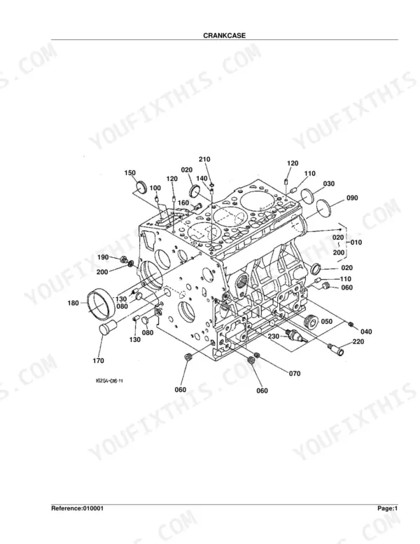
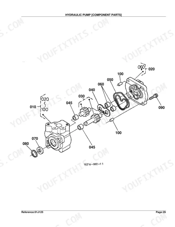
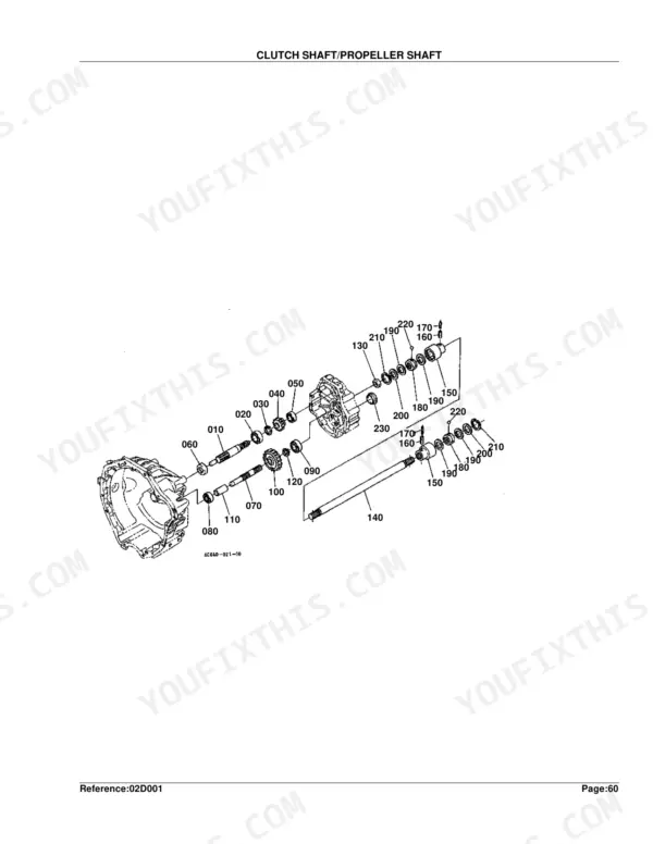
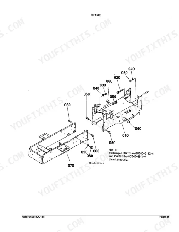
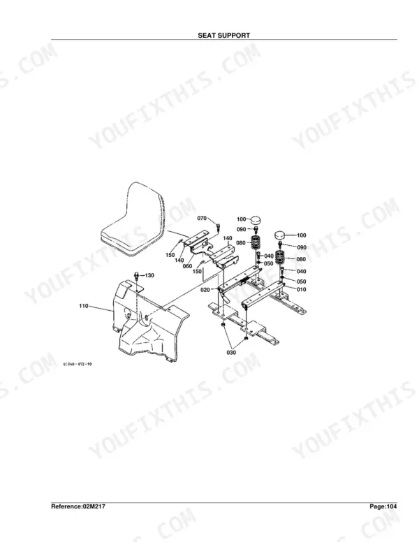
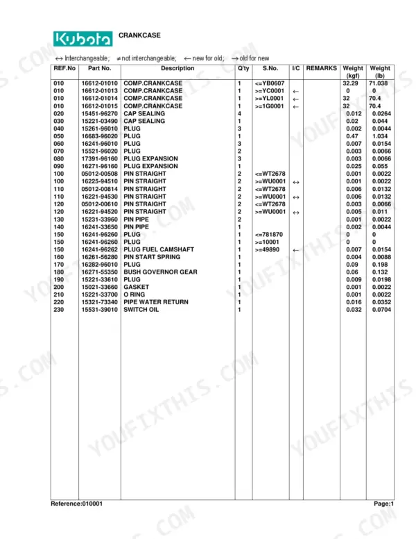
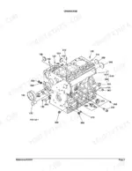
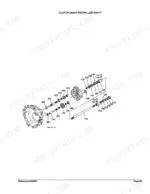
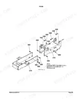
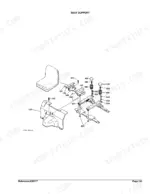
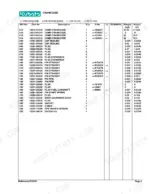
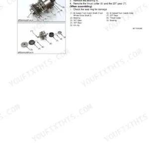
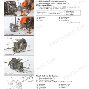
This is the Kubota B2100D parts catalog, a downloadable PDF that lists every factory part number for this compact 4WD diesel tractor. Its 269 pages break the machine down assembly by assembly, from the crankcase, injection pump and governor through the clutch, hydraulic pump, transmission, front axle, brakes and complete electrical wiring.
Every section pairs an exploded diagram with a numbered parts list and serial-number ranges, so you can pinpoint the exact component and order the correct replacement the first time. It is the reference to reach for when you are rebuilding the engine, tracking a no-start to the stop solenoid, or sourcing worn brake and front-wheel parts.
This is a parts identification catalog rather than a service manual, but for B2100D owners and independent mechanics it removes the guesswork from finding and ordering genuine Kubota parts on any device.
Complete the set for your B2100D
- Repair Manual: Kubota B1700, B2100, B2400 Shop Manual — Wiring Diagrams
What's Inside This Kubota B2100D Parts Manual
| System | Pages | Key Topics |
|---|---|---|
| Clutch & Transmission | Clutch, Clutch Rod, Clutch Pedal, Clutch Housing, Transmission Case, Clutch Shaft/Propeller Shaft, 2Nd Shaft/3Rd Shaft/4Th Shaft, Main Gear Shift Fork, Main Gear Shift Lever, Range Gear Shift Lever, PTO Gear Shift Lever | |
| Fuel System | Fuel Camshaft and Governor Shaft, Stop Solenoid, Injection Pump, Governor, Speed Control Plate, Nozzle Holder and Glow Plug, Nozzle Holder, Air Cleaner, Accelerator Lever, Fuel Tank, Fuel Pipe, Fuel Filter | |
| Cooling System | Water Flange and Thermostat, Water Pump, Fan, Water Pipe, Radiator | |
| Engine | Crankcase, Oil Pan, Cylinder Head, Gear Case, Head Cover, Main Bearing Case, Camshaft and Idle Gear Shaft, Piston and Crank Shaft, Flywheel, Valve and Rocker Arm, Inlet Manifold, Exhaust Manifold, Upper Gasket Kit, Lower Gasket Kit, Muffler, Differential Gear Case | |
| Electrical System | Dynamo, Alternator, Starter, Battery, Panel Board, Head Light, Tail Light/Hazard Light/Working Light, Electrical Wiring, Stater Relay Kit | |
| Undercarriage & Travel | Steering Controller | |
| PTO | 5Ht Shaft/PTO Shaft, Mid PTO | |
| Rear Axle, Differential & Brakes | Rear Axle Case, Rear Differential, Rear Axle, Brake, Parking Brake Lever, Brake Pedal, Differential Lock Pedal, Front Axle Case, Rear Wheel | |
| Front Axle & Steering | Front Wheel Propeller Shaft, Front Wheel Drive Lever, Front Differential, Front Axle, Front Drive Shaft, Drag Link, Tie Rod, Steering Handle, Front Wheel | |
| Hydraulics & 3-Point Hitch | Hydraulic Pump, Hydraulic Oil Line, Flow Divider Valve, Hydraulic Cylinder Case, Control Valve, Lift Rod, Lower Link, Top Link | |
| Body & Operator Station | Frame, Front Grille, Hood, Side Cover, Fender, Seat Support, Seat, Step, ROPS | |
| Decals & Accessories | Label, Accessories and Service Parts | |
| Other Components | Positon Control Lever |
Quick Reference Specifications
| Specification | Value | Page |
|---|---|---|
| Fuse | 30A | p. 118 |
| Fuse Auto | 5A | p. 118 |
| Bulb Light | 27W | p. 116 |
| Front Wheel Size | 6-12 | p. 4 |
| Rear Wheel Size | 9.5-16 | p. 4 |
| Piston Oversize | +0.50mm | p. 23 |
| Metal Crankpin Undersize | -0.20mm SET | p. 23 |
| Nozzle Holder Adjusting Washer Thickness | 0.10MM | p. 44 |
| Tail Light Bulb Power Rating | 27W | p. 116 |
| Main Fuse Rating | 30A | p. 118 |
| Gear Clutch Shaft Tooth Count | 16T | p. 140 |
| Gear Reverse Tooth Count | 16-20T | p. 152 |
Kubota B2100D Common Problems This Manual Covers
Shuts off with a clicking no-start
A B2100D that shuts off and clicks instead of starting is often an electrical supply fault, frequently the fuel stop solenoid. This section shows the solenoid assembly and part numbers to replace it.
Manual Section: Stop Solenoid p. 28Blown fuses and electrical faults
Blown fuses and intermittent wiring problems are common on older compact tractors. The Electrical Wiring section identifies the harness, fuses and connectors you need to source.
Manual Section: Electrical Wiring p. 117Weak or uneven brakes
Brake wear and adjustment are recurring concerns on the B2100D. This section lays out the brake components so you can identify worn parts and order the correct replacements.
Manual Section: Brake p. 158Front-wheel wobble or runout
Front-wheel vibration and rim runout usually trace to a worn bearing, hub or rim. This section provides the front axle assembly and part numbers to rebuild the front-wheel end.
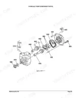
Manual Section: Front Axle p. 187Weak hydraulic lift
When the three-point lift becomes slow or weak, the hydraulic pump is a common cause. This section shows the pump and its component parts for ordering seals and internals.
Manual Section: Hydraulic Pump p. 67Starter will not crank
A no-crank condition often points to a failing starter. This section gives the starter and its component parts so the unit can be rebuilt or replaced.
Manual Section: Starter p. 101Frequently Asked Questions
Which tractor does this parts catalog cover?
It covers the Kubota B2100D compact 4WD diesel tractor, listing part numbers and exploded diagrams for its engine, drivetrain, hydraulic, brake and electrical assemblies.
Is this a parts catalog or a service manual?
This is a parts catalog. It provides exploded diagrams, part numbers and quantities for ordering components, not step-by-step repair or troubleshooting instructions.
Where do I find fuse part numbers?
The Electrical Wiring section, starting on page 117, covers the harness, fuses and connectors, including the 30A main fuse used on the B2100D. p. 117
Can I order hydraulic pump parts from it?
Yes. The Hydraulic Pump section, from page 67, shows the exploded view and part numbers for the pump and its component parts. p. 67
How quickly can I access this manual after buying?
A 269-page searchable PDF, ready to download the moment you buy. It works on any device, so you can pull it up on your phone while you are under the hood. No shipping, no waiting.
Is this Kubota B2100D Parts Catalog printable?
Yes. Print the sections you need to take out to the shop for your own use. Standard letter or A4 paper works.


Reviews
There are no reviews yet.