

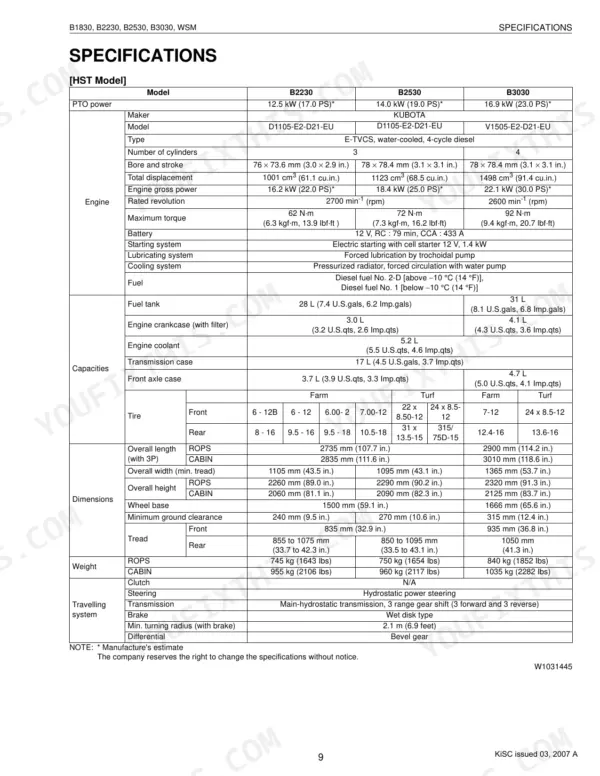
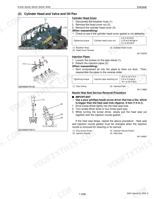


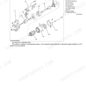
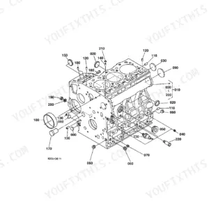
This is the Kubota factory workshop manual for the B1830, B2230, B2530 and B3030 compact tractors, a 526-page PDF for the machines powered by Kubota's D905, D1005, D1105 and V1505 (E2 series) diesel engines. Written for servicing personnel, it covers mechanism, troubleshooting, servicing specifications, tightening torques and step-by-step disassembly and reassembly.
Coverage runs system by system: engine, clutch, transmission (manual and hydrostatic), rear axle, brakes, front axle, steering, the hydraulic system, the electrical system with full wiring diagrams, and the cabin air conditioning system. Each section lists its own factory specifications and allowable limits.
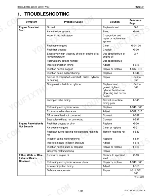
Owners and independent mechanics can use this download to trace a no-start, restore weak hydraulics or three-point-hitch lift, set the correct wheel and axle torques, or rebuild a worn assembly following the factory procedure. Any page prints cleanly for use at the machine.
Complete the set for your B1830–B3030 Series
- Operator Manual: Kubota B2630, B3030, B3000 Operator Manual
What's Inside This Manual
| System | Pages | Key Topics |
|---|---|---|
| To the Reader | Engine, Hydraulic System, PTO System, Transmission, Brake, Differential, ROPS, Cabin | |
| G General | Tractor Identification, General Precautions, Wiring, Battery, Fuse, Connector, Handling of Circuit Tester, Lubricants Fuel and Coolant | |
| Engine | Tractor Section, Engine Section, Preparation | |
| Clutch | Manual Transmission Model, Clutch Operation | |
| Transmission | HST (with Bi-Speed Turn Model), Front Case, Bi-Speed Turn Linkage, Bi-Speed Turn Powertrain, Manual Transmission, Hydrostatic Transmission, Pump and Motor, Oil Flow and Valves | |
| Rear Axle | Differential Gear Shaft, Ball Bearing, Rear Axle Case, Spur Gear, Spiral Bevel Gear, Differential Gear, Differential Lock Shift Fork | |
| Brakes | Operation | |
| Front Axle | 4 Wheel Drive Model | |
| Steering | Hydraulic Circuit, Steering Controller, Steering Cylinder | |
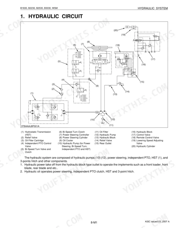
| Hydraulic System | Hydraulic Circuit, Hydraulic Pump, Hydraulic Block, Power Steering, Power Steering Controller, Steering Cylinder, Independent PTO, Independent PTO Control Valve | |
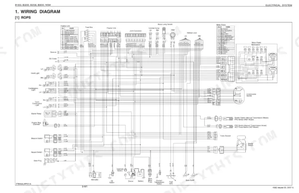
| Electrical System | Wiring Diagram, ROPS, Cabin, Starting System, Starter, Glow Plug, Safety Switch, Engine Stop Solenoid | |
| Cabin | Outline of Air Conditioning System, Air Flow, Air Control Vent, Control Panel, Operation, Refrigeration System, Compressor, Condenser |
Every system also includes disassembling and servicing, tightening torques, troubleshooting, checking, and servicing specifications.
Quick Reference Specifications
| Specification | Value | Page |
|---|---|---|
| B3030 | ||
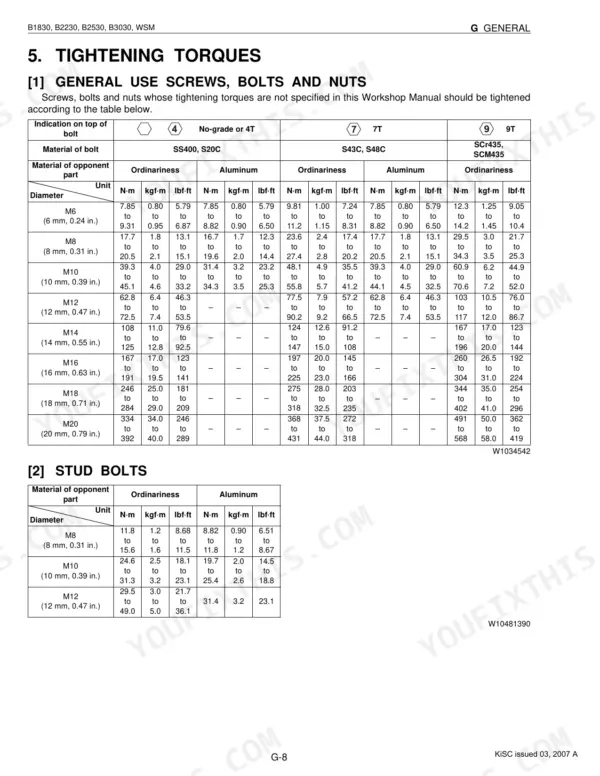
| Rear wheel mounting bolt (M14) | 196 to 225 N·m | p. 296 |
| PTO Power | 16.9 kW (23.0 PS) | p. 11 |
| All Models | ||
| Front wheel mounting bolt and nut | 77.0 to 90.0 N·m | p. 323 |
| Front axle holder mounting bolt | 200 to 230 N·m | p. 327 |
| Engine oil filter replacement interval | every 200 Hr | p. 29 |
| Fuel filter element replacement interval | every 400 Hr | p. 29 |
| Air cleaner element replacement interval | every 1 year | p. 29 |
| Air conditioner condenser screen cleaning interval | Daily | p. 29 |
| Battery | 12 V, RC : 79 min, CCA : 433 A | p. 11 |
| Fan belt tension | A deflection of between 7 to 9 mm (0.28 to 0.34 in.) | p. 43 |
| Transmission oil filter replacement interval | every 300 Hr | p. 29 |
| B1830, B2230, B2530 | ||
| Rear wheel hub mounting nut | 108 to 125 N·m | p. 296 |

