
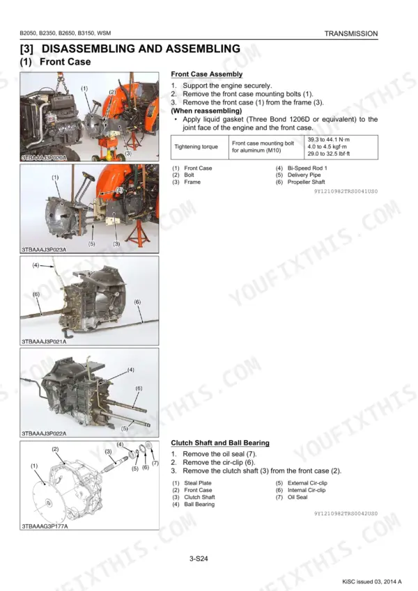
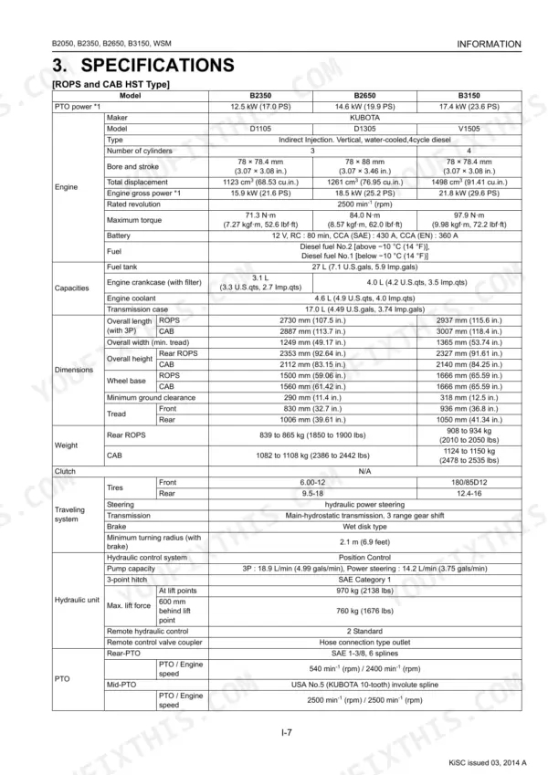
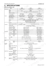
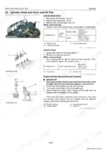
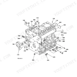
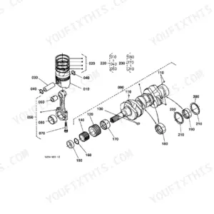
This is the Kubota factory workshop manual for the B2050, B2350, B2650 and B3150 compact tractors, a 539-page PDF covering the machines built around Kubota's D1105, D1305 and V1505 diesel engines. It is written for the servicing technician, combining mechanism descriptions, troubleshooting charts, servicing specifications and tightening torques with full disassembly and reassembly procedures.
The manual is organized by system: engine, clutch, transmission (manual and HST), rear axle, brakes, front axle, steering, hydraulics, the electrical system with wiring diagrams, and the cabin air conditioning system. Each system carries its own factory specs and allowable limits.
With this download an owner or independent mechanic can diagnose a fault, look up the correct torque or clearance, and follow the factory sequence for repairs such as a weak three-point hitch, a start-safety interlock problem, or an HST that has lost drive. Print any page you need for the shop.
What's Inside This Kubota B2050–B3150 Series Manual
| System | Pages | Key Topics |
|---|---|---|
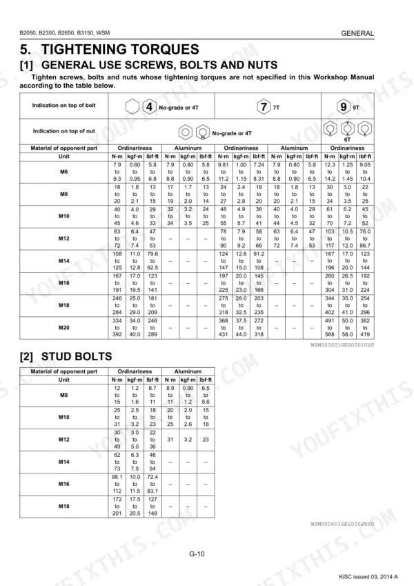
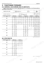
| G General | Tractor Identification, Handling Precautions for Electrical Parts and Wiring (Wiring, Battery, Fuse, Connector, Handling of Circuit Tester, Color of Wiring), Lubricants, Fuel and Coolant, Tightening Torques (Stud Bolts, Metric Screws, Bolts and Nuts, American Standard Screws, Bolts and Nuts with Unc or Unf Threads, Plugs), Maintenance Check List, Check and Maintenance (Daily Check, Check Points of Every 50 Hours, Check Points of Every 100 Hours, Check Points of Every 200 Hours, Check Points of Every 400 Hours, Check Point of Every 800 Hours, Check Point of Every 1500 Hours, Check Point of Every 3000 Hours, Check Points of Every 1 Year, Check Points of Every 2 Years, Others), Special Tools (Special Tools for Engine, Special Tools for Tractor, Special Tools for Cabin), Tires (Tire Pressure, Wheel Adjustment, Ballast), Implement Limitations | |
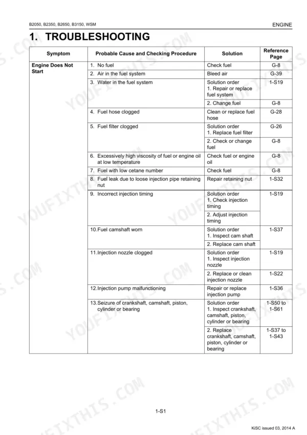
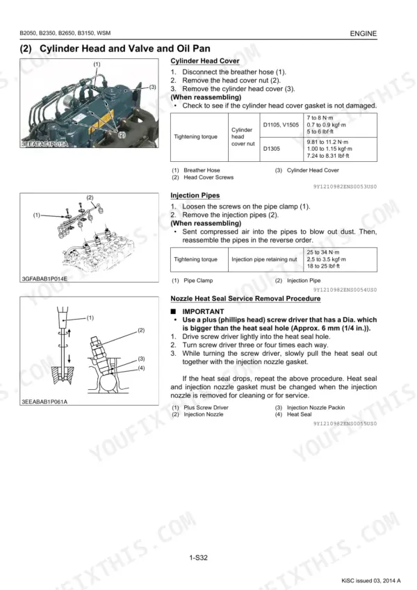
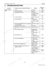
| Engine | Engine Body (Closed Breather [D1105, V1505], Half-Floating Head Cover [D1305], Governor), Troubleshooting, Servicing Specifications, Tightening Torques (Tractor Section, Engine Section), Checking, Disassembling and Servicing (Checking and Adjusting, Preparation, Disassembling and Assembling, Servicing) | |
| Clutch | Structure (Manual Transmission Model, Clutch Operation), Troubleshooting, Servicing Specifications, Tightening Torques, Checking, Disassembling and Servicing (Checking and Adjusting, Disassembling and Assembling, Servicing) | |
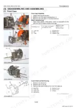
| Transmission | Structure (Manual Transmission, HST), Front Case (Structure, Bi-Speed Turn Linkage, Bi-Speed Turn Powertrain), Manual Transmission (Structure), Hydrostatic Transmission (Structure, Pump and Motor, Oil Flow and Valves, Control Linkage), Cruise Control (Cruise Control Linkage [Cabin Model], Cruise Control Linkage), Range Gear Shift Section, Front Wheel Drive Section, PTO System (Structure, Rear PTO Section, Rear PTO / Mid-PTO Section, Mid-PTO Section, Independent PTO), Differential Gear System (Differential Function, Differential Lock), Troubleshooting, Servicing Specifications, Tightening Torques, Checking, Disassembling and Servicing (Checking and Adjusting, Preparation, Disassembling and Assembling, Servicing) | |
| Rear Axle | Structure, Troubleshooting, Tightening Torques, Diassembling and Servicing (Diassembling and Assembling, Servicing) | |
| Brakes | Linkage (ROPS, Cabin), Operation, Troubleshooting, Servicing Specifications, Tightening Torques, Checking, Disassembling and Servicing (Checking and Adjusting, Disassembling and Assembling, Servicing) | |
| Front Axle | Structure (Wheel Drive Model), Troubleshooting, Servicing Specifications, Tightening Torques, Checking, Disassembling and Servicing (Checking and Adjusting, Disassembling and Assembling, Servicing) | |
| Steering | Hydraulic Circuit, Steering Controller, Steering Cylinder, Hydraulic Pump, Troubleshooting, Servicing Specifications, Tightening Torques, Checking, Disassembling and Servicing (Checking, Disassembling, Servicing) | |
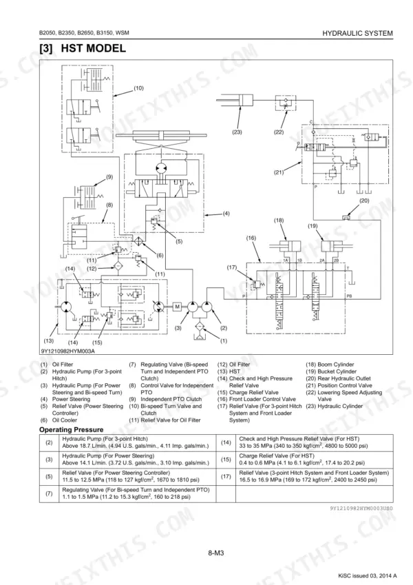
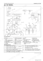
| Hydraulic System | Hydraulic Circuit (Manual Transmission Model, HST Model), Hydraulic Pump, Three Points Hydraulic System (Hydraulic Circuit, Relief Valve, Position Control Valve, Feedback Linkage for Position Control), Front Loader Control Valve (Structure, Operation), Remote Control Valve, Hydraulic Outlet (Manual Transmission Model, Troubleshooting, Servicing Specifications, Tightening Torques, Checking, Disassembling and Servicing (Checking and Adjusting, Disassembling and Assembling, Servicing) | |
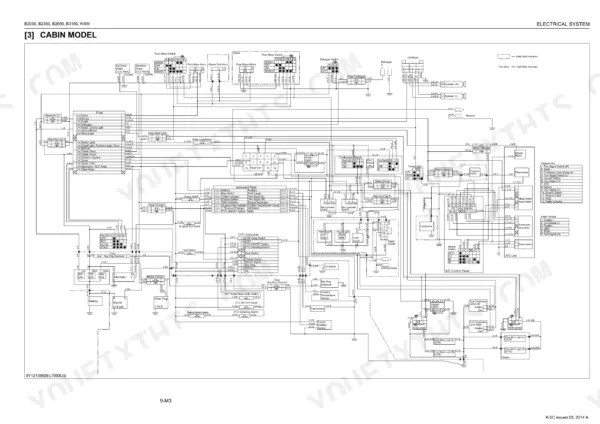
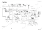
| Electrical System | Wiring Diagram (ROPS Model, B3150 ROPS, Cabin Model), Engine Starting System and Stopping System (Opc System Circuit, Controller, Safety Switch, Starter, Key Stop Solenoid, Glow Plug), Charging System (Alternator, Ic Regulator), Lighting System (Head Light, Turn Signal Light, Hazard Light, Beacon, Brake Light, Work Light, Trailer Socket), Instrument Panel (Easy Checker™, Gauges and Other Indicators, Error Code Display, Switches and Sensors), Troubleshooting, Servicing Specifications, Tightening Torques, Checking and Adjusting (Battery, Fuse, Relays, Starting System, Charging System, Lighting System, Warning Lamp, Indicator Lamp and Gauge), Disassembling and Assembling (Starter, Alternator), Servicing (Starter | |
| Cabin | Outline of Air Conditioning System (Structure, Air Conditioning System), Refrigeration System (Compressor, Condenser, Receiver, Air Conditioner Unit), System Control, Electrical System (Electrical Circuit, Relay), Troubleshooting, Servicing Specifications, Tightening Torques, Precautions at Repairing Refrigerant Cycle (Handling of Service Tools), Checking and Charging Refrigerant Cycle (Checking with Manifold Gauge, Discharging, Evacuating and Charging), Checking, Disassembling and Servicing (Checking and Adjusting, Disassembling and Assembling, Servicing) |
Documents This Manual Refers To
The manufacturer cites these publications by number. We carry them:
Quick Reference Specifications
| Specification | Value | Page |
|---|---|---|
| All Models | ||
| Front axle holder mounting bolt | 200 to 230 N·m | p. 315 |
| Front wheel mounting nut | 77 to 90 N·m | p. 42 |
| Seat Switch Continuity (Operator on the seat) | 0 Ω | p. 445 |
| PTO Clutch Lever Switch Continuity (disengaged) | 0 Ω | p. 445 |
| Hydraulic Oil Filter Tightening | Tighten by hand an additional 1/2 turn only | p. 56 |
| Transmission fluid type | KUBOTA UDT or SUPER UDT fluid | p. 29 |
| Transmission case capacity (HST Type) | 17 L | p. 29 |
| Hydraulic Pump (For 3-Point Hitch) Delivery (At Rated Pressure) | Above 18.3 L/min. | p. 370 |
| B2650 | ||
| Rear wheel mounting nut and screw | 108 to 126 N·m | p. 42 |
| Manual transmission model | ||
| Shuttle shift lever switch Continuity (neutral) | 0 Ω | p. 445 |
| HST model | ||
| HST Pedal Switch Continuity (neutral) | 0 Ω | p. 445 |
| Manual Transmission Model | ||
| 3-Points Hitch Relief Valve Setting Pressure | 15.5 to 16.5 MPa | p. 377 |
Kubota B2050–B3150 Series Common Problems This Manual Covers
Three-point hitch weak or intermittent
A three-point hitch that stops lifting or becomes intermittent is a common B2650 complaint, usually a hydraulic issue such as low fluid, a clogged filter, or a failing pump or control valve. This section covers the hydraulic circuit, relief valve and position control.
Manual Section: 8 Hydraulic System p. 342Engine cranks with operator off the seat
When the start or PTO interlock behaves incorrectly, the fault usually lies in the seat switch, PTO switch or neutral safety circuit. This section covers the safety switches, wiring and continuity checks for the interlock system.
Manual Section: 9 Electrical System p. 391HST or transmission sluggish
A hydrostatic transmission that feels weak or hesitant can stem from fluid condition, control linkage, or internal wear. This section details the HST structure, oil flow and valves along with checking and servicing procedures.
Manual Section: 3 Transmission p. 165Hard starting or engine fault
Difficult starting and rough running are traced through the engine troubleshooting charts and servicing specifications. This section walks through checking, disassembling and servicing the engine to factory limits.
Manual Section: 1 Engine p. 84Uneven or weak braking
Brake wear and adjustment are recurring items on working tractors. This section covers brake linkage, operation, servicing specifications and the checking-and-adjusting procedure.
Manual Section: 5 Brakes p. 288Cabin air conditioning not cooling
Poor cooling in cabin models usually involves the refrigerant cycle, compressor or relays. This section covers the air conditioning system, refrigerant charging and troubleshooting for the cabin.
Manual Section: 10 Cabin p. 474Frequently Asked Questions
Which models and engines does this manual cover?
It covers the Kubota B2050, B2350, B2650 and B3150 tractors, which use Kubota's D1105, D1305 and V1505 diesel engines.
Is this the full factory workshop manual?
Yes. It includes mechanism descriptions, troubleshooting, servicing specifications, tightening torques and full disassembly and reassembly procedures across all major systems.
What are the front axle bolt torques?
Front axle torque values are in the Front Axle section from page 306, including the front axle holder mounting bolt at 200 to 230 N·m. p. 306
What is the three-point hitch relief valve pressure?
The Hydraulic System section, from page 342, sets the three-point hitch relief valve at 15.5 to 16.5 MPa on manual transmission models and 16.5 to 16.9 MPa on HST models. p. 342
Is this Kubota B2050–B3150 Series manual a PDF I download?
Right after checkout you can download the 539-page searchable PDF. It opens on a laptop, tablet, or phone, so you can bring it straight to the shop floor.
Can I print pages of this manual for my own shop?
Yes. Printing works from any reader and any printer, for your own shop use.
Does this Kubota B2050–B3150 Series manual show the machine's wiring?
Yes, this Kubota B2050, B3150 Workshop Manual includes complete electrical wiring diagrams, wire routing, and connector pinouts.


Reviews
There are no reviews yet.