
This is the Kubota B2650 and B2660 Snowblower Operator's and Parts Manual (form 251551), the factory book for these front-mount snowblowers and the tractors they attach to. Its 50 pages combine setup, operation, maintenance, and a full illustrated parts breakdown.
It walks through sub-frame and snowblower installation, hydraulic connections and adjustments, the torque tightening chart, lubrication and maintenance, and operating instructions for chute rotation, lifting, and snow removal. Specifications list impeller and auger speeds, cutting width, and chute rotation, and the parts illustrations give replacement part numbers.
For an owner fitting or servicing the blower, it covers the common headaches, a lift that only works at idle, inconsistent chute or lift action after setup, and shear bolt or drive chain failures, with the part numbers and torque values needed to put it right.
What's Inside This Kubota B2650, B2660 Operator Manual
| System | Pages | Key Topics |
|---|---|---|
| Safety Precautions | Before Operation, Maintenance | |
| Safety Signs | Safety Sign Locations, Care of Safety Signs, Sign Illustrations & Part Numbers | |
| Specifications | Authorized Tractor Applications | |
| Tractor Preparation | Steering Stop Plate Installation | |
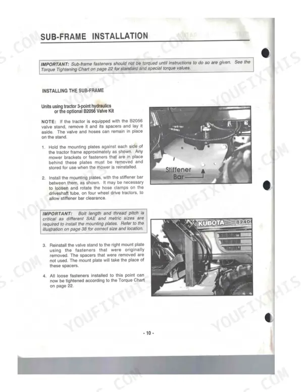
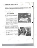
| Sub-Frame Installation | Installing the Sub-Frame, Units Using 3-Point Hydraulics or the B2056 Valve Kit, Units with Front Loader, All Unit Combinations, Installing Handle Support, Hydraulic Connections | |
| Hydraulic Adjustments | 3-Point Hydraulic Control Valve Return Spring (Lever Is Moved Too Far Forward, Hydraulic Relief Remains Partially Activated) | |
| Additional Assembly Information | Important Notes, Pre-Delivery Inspection, Hydraulic Control Valve Return Spring Adjustments, Drive Shield Exchange | |
| Snowblower Installation | Fastening to the Lift Frame, Installing the Chute, Installing the Chute Handle, Connecting the Driveshafts, Skid Shoe Adjustment | |
| Torque Tightening Chart | Standard Torque Application Chart (Sae Grade 5, Metric Grade 8.8), Special Torque Applications (B2400 Tractor Front Axle Housing, Sub-Frame Fasteners) | |
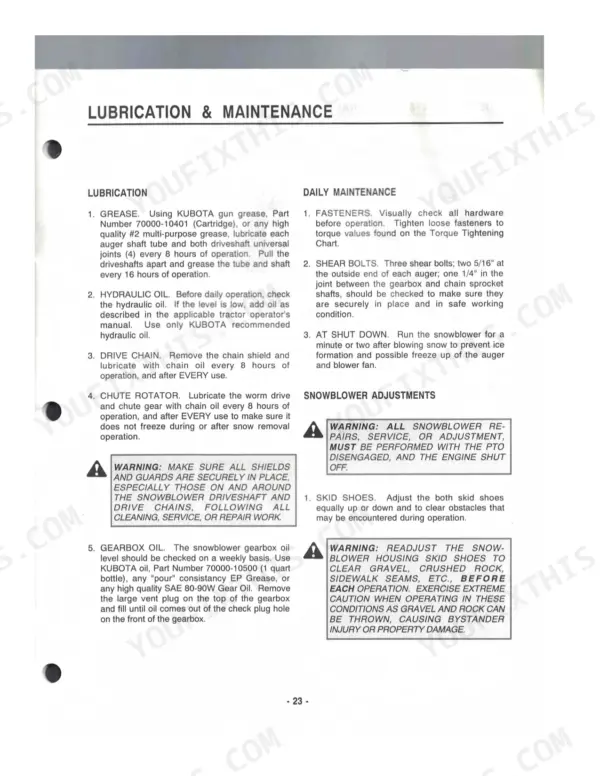
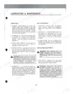
| Lubrication & Maintenance | Lubrication, Daily Maintenance, Snowblower Adjustments (Skid Shoes, Drive Chain, Chute Deflector) | |
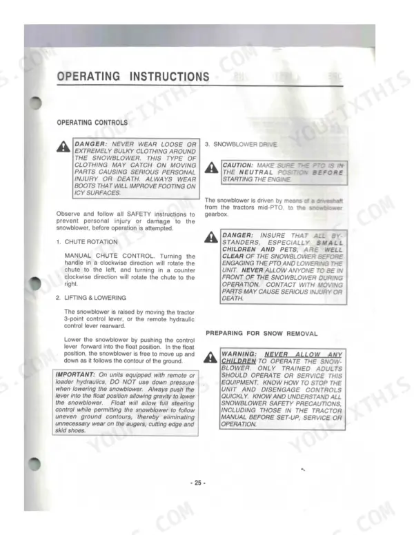
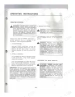
| Operating Instructions | Operating Controls (Chute Rotation, Lifting & Lowering, Snowblower Drive), Preparing for Snow Removal, Removing Snow, Transporting the Snowblower | |
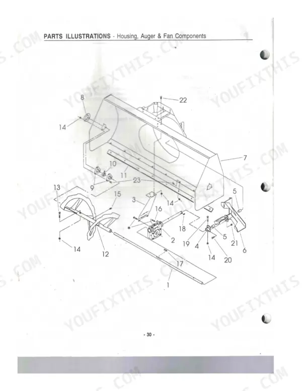
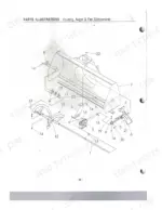
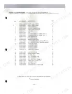
| Parts Illustrations | Housing, Auger & Fan Components, Drive Components, Discharge Chute Components, Gearbox Components, Sub-Frame Components, Hydraulic Lift Components, Driveshaft Components |
Quick Reference Specifications
| Specification | Value | Page |
|---|---|---|
| Front Axle Housing Bolt Torque (M12-1.25 x 45) | 91-108 ft. lbs. (123.5-147.0 N•m) | p. 9 |
| Front Axle Housing Nut Torque (M12-1.25) | 62-75 ft. lbs. (84.0-101.8 N•m) | p. 9 |
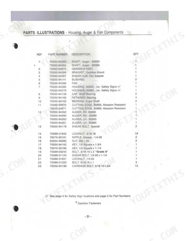
| Auger Shear Bolt Replacement Part Number | 70050-94176 | p. 32 |
| Fan Adapter Shear Bolt Replacement Part Number | 75599-01125 | p. 32 |
| Drive Chain Deflection | 1/8 to 3/16 of an inch | p. 25 |
| Drive Chain Replacement Part Number | 70050-94276 | p. 34 |
| Gearbox Pin (M8 x 35) Replacement Part Number | 70050-94223 | p. 38 |
| Gearbox Pin (M6 x 12) Replacement Part Number | 70050-94224 | p. 38 |
| Hydraulic Hose (1/4 x 28) Replacement Part Number | 70050-94515 | p. 42 |
| Quick Disconnect Coupler Replacement Part Number | 75532-66323 | p. 42 |
| Overall Length | 132.2" (3558 mm) | p. 7 |
Kubota B2650, B2660 Common Problems This Manual Covers
Blower rises only at engine idle
A front blower that will only lift at idle usually has a hydraulic flow or pressure issue, a sticky lift cylinder, or a connection fault in the front-mount circuit. The Hydraulic Adjustments section covers the control valve return spring.
Manual Section: Hydraulic AdjustmentsChute or lift inconsistent after setup
Lift or chute functions that misbehave after installation often mean hoses, couplers, or linkage that are not fully seated or are routed wrong. The Sub-Frame Installation section covers the hydraulic connections.
Manual Section: Sub-Frame InstallationBlower stops turning under load
If the blower stops turning while the drive still runs, the auger or fan shear bolt has likely failed to protect the gearbox. The Snowblower Installation section covers the driveshaft connections and drive components.
Manual Section: Snowblower InstallationDrive chain loose or noisy
A loose or noisy drive chain needs its deflection reset within spec so it does not jump or wear the sprockets. The Lubrication and Maintenance section covers drive chain adjustment and lubrication.
Manual Section: Lubrication & MaintenanceMounting hardware loosens in use
Attachment and sub-frame fasteners can loosen from vibration if they are not rechecked to spec after the first use. The Torque Tightening Chart section lists the standard and special torque values.
Manual Section: Torque Tightening ChartWeak or clogged snow discharge
Weak throwing distance or a clogging chute usually comes from technique, snow condition, or auger and impeller wear rather than a fault. The Operating Instructions section covers chute rotation and snow removal.
Manual Section: Operating InstructionsFrequently Asked Questions
Which snowblowers and tractors does this cover?
It covers the Kubota B2650 and B2660 front-mount snowblowers and lists the authorized tractor applications they mount to. It is the factory Operator's and Parts Manual, form 251551.
What specifications does it list?
The Specifications section lists the snowblower dimensions and performance, including impeller speed of 903 RPM, auger speed of 181 RPM, cutting width, and 200 degrees of chute rotation. p. 7
Does it include torque specs?
Yes. The Tractor Preparation section gives the steering stop bolt torque of 91-108 ft. lbs. (123.5-147.0 N•m), and the torque tightening chart and sub-frame fastener values are also included. p. 9
Does it list replacement part numbers?
Yes. The parts illustrations give replacement part numbers, such as the auger shear bolt (70050-94176), fan adapter shear bolt (75599-01125), and drive chain (70050-94276).
Do I get instant access to this Kubota B2650 Operator Manual?
A 50-page Operator Manual in searchable PDF format, available the moment you complete checkout. View on computer, tablet, or phone (no shipping wait).
Can I print a copy of this Kubota B2650 Operator Manual for the shop?
Yes. Print a chapter or just the pages for the job at hand, for use in your own shop. Any home or office printer works.

Reviews
There are no reviews yet.