
Part of the Kubota Repair Manuals.
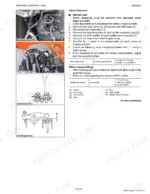
This is the Kubota Workshop Manual for the B2650HSDC and B3350HSDC compact tractors, publication 9Y111-08220. Its 470 pages cover both models, built from 2014 to 2018, including the D1305-E4-D26-Q and turbocharged V1505-T-E4-D26-Q diesel engines and their exhaust aftertreatment (DPF) system.
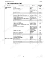
Inside you get engine, transmission, axle, brake, steering, hydraulic, electrical, and cab coverage, with troubleshooting, servicing specifications, and tightening torques. Wiring diagrams, safety-switch resistance values, relief-valve pressures, and wheel torques are listed with their pages, along with fluid capacities and service intervals for the fuel, hydraulic, and engine oil filters.
For an owner or independent shop, this download is the tool for diagnosing a no-start after shutdown, a cold-weather stall, or weak hydraulics, and for making the repair to Kubota specification instead of paying dealer rates.
What's Inside This Kubota B2650HSDC, B3350HSDC Manual
| System | Pages | Key Topics |
|---|---|---|
| To the Reader | Information | |
| G General | Tractor Identification, Model Name and Serial Number, Cylinder Number, General Precautions, Wiring, Battery, Fuse, Connector | |
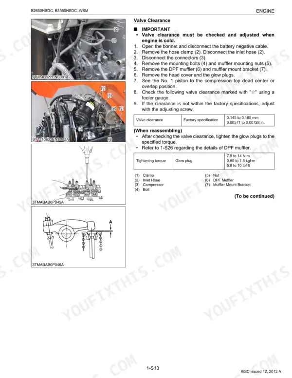
| Engine | Engine Body, Closed Breather, Half-Floating Head Cover, Engine Control System [V1505-T-E4], Electronic Governor [V1505-T-E4], Governor [D1305-E4], Reformer and After Treatment Devices, Reformer | |
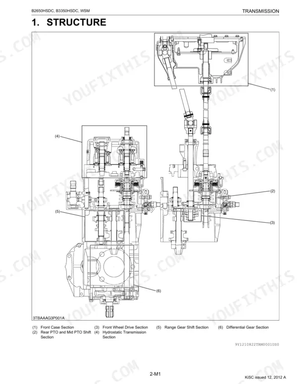
| Transmission | Front Case, Hydrostatic Transmission, Pump and Motor, Oil Flow and Valves, Control Linkage, Cruise Control, Cruise Control Linkage, Range Gear Shift Section | |
| Rear Axle | Excessive or Unusual Noise at All Time, Noise While Turning, Rear Wheel Mounting Nut, Rear Wheel Mounting Bolt, Front Loader Valve Pipe Joint Bolt, 3-Point Hitch Delivery Pipe 1 Joint Bolt, 3-Point Hitch Delivery Pipe Joint Bolt, Rear Axle Case Mounting Screw | |
| Brakes | Linkage, Operation, During Braking, Uneven Braking Force, Brake Drags, Poor Braking Force, Brake Pedal, Cam Plate and Bearing Holder | |
| Front Axle | 4 Wheel Drive Model, Front Wheels Wander to Right or Left, Front Wheels CAN Not Be Driven, Noise, Front Wheel Alignment, Differential Pinion to Deferential Case, Yoke Shaft to Differential Case | |
| Steering | Hydraulic Circuit, Steering Controller, Steering Cylinder, Hydraulic Pump | |
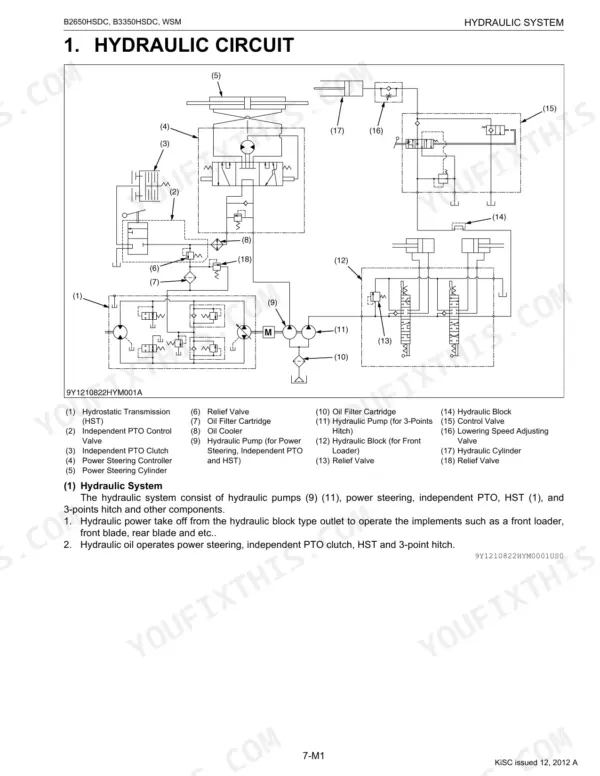
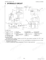
| Hydraulic System | Hydraulic Circuit, Hydraulic Pump, Three Points Hydraulic System, Front Loader Control Valve, 3-Point Hitch Control Valve, Relief Valve, Position Control Valve, Feedback Linkage for Position Control | |
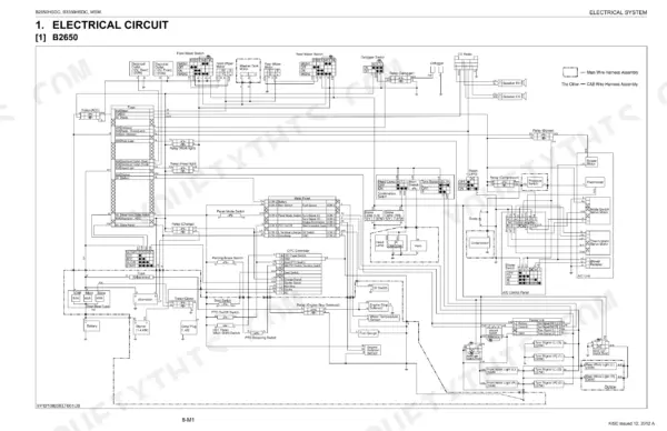
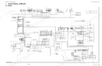
| Electrical System | Electrical Circuit, B2650, B3350, Engine Starting System and Stopping System, Opc System Circuit (B2650), Opc System Circuit (B3350), Controller, Safety Switch | |
| Cabin | Air Conditioner System, Outline of Air Conditioning System, Refrigeration System, Compressor, Condenser, Receiver, Air Conditioner Unit, System Control |
Quick Reference Specifications
| Specification | Value | Page |
|---|---|---|
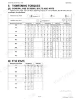
| Rear wheel mounting nut torque | 167 to 191 N·m (17 to 19.5 kgf·m, 123 to 141 lbf·ft) | p. 38 |
| Rear wheel mounting bolt torque | 200 to 220 N·m | p. 38 |
| Battery (Volt) | 12 V | p. 40 |
| Battery (Capacity at 5 H.R.) | 36 | p. 40 |
| Engine Stop Solenoid Relay (Resistance) | 0 Ω | p. 397 |
| Seat switch (Operator on the seat) | 0 Ω | p. 373 |
| Seat switch (Vacant) | Infinity | p. 373 |
| Fuel filter element (Clean interval) | every 100 hours | p. 29 |
| Fuel filter element (Replace interval) | every 400 hours | p. 29 |
| Transmission oil filters (Replace interval) | every 300 hours | p. 29 |
| Engine oil filter (Replace interval) | every 200 hours | p. 29 |
| Charge Relief Valve Setting Pressure | 0.4 to 0.6 MPa (4 to 6 kgf/cm², 60 to 80 psi) | p. 194 |
Kubota B2650HSDC, B3350HSDC Common Problems This Manual Covers
No-start or no-crank after shutdown
A no-start or no-crank condition after the tractor shuts off usually points to a safety interlock, battery, or relay fault. The Electrical System section covers the starting system, controller, safety switches, and their resistance values.
Manual Section: 8 Electrical System p. 337Hard starting in cold weather
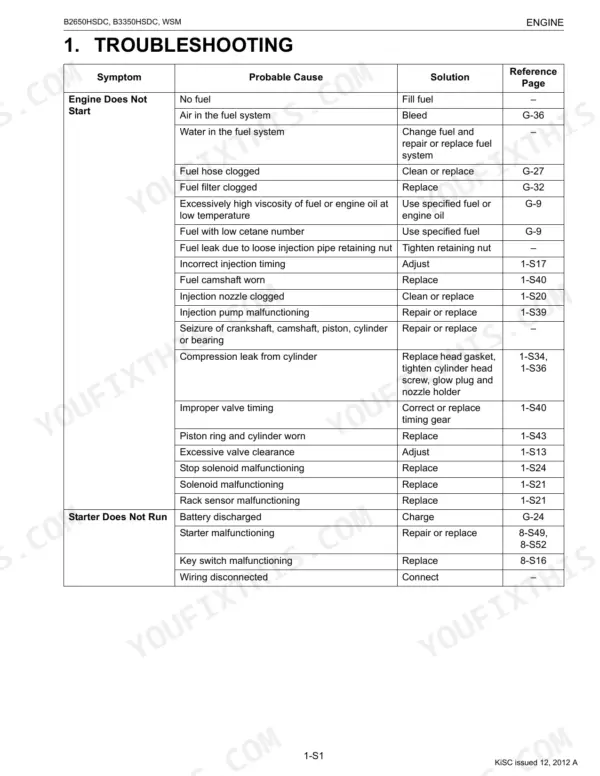
Hard starting or a stall in cold weather can come from a weak battery, the starting circuit, or a fuel-related fault. The Engine section provides troubleshooting and the engine control and governor details to diagnose it.
Manual Section: 1 Engine p. 79Weak or slow hydraulics
Slow or weak hydraulic and loader performance often traces to low or contaminated fluid, a clogged filter, or a relief valve out of spec. The Hydraulic System section lists pump delivery and relief valve pressures.
Manual Section: 7 Hydraulic System p. 301HST creeps or loses drive
A hydrostatic transmission that creeps in neutral or loses drive can have a charge relief valve, worn piston slippers, or fluid problems. The Transmission section gives the charge relief pressure and wear limits.
Manual Section: 2 Transmission p. 159Weak or spongy brakes
Brakes that feel weak or need extra travel usually need pedal free travel adjustment or disc service. The Brakes section gives the free travel spec and the checking procedure.
Manual Section: 4 Brakes p. 251Cab air conditioning not cooling
Weak cab cooling can trace to the air conditioner magnetic clutch air gap or a refrigeration fault. The Cabin section covers the compressor, condenser, receiver, and system control.
Manual Section: 9 Cabin p. 408Frequently Asked Questions
Which models does this manual cover?
It covers the Kubota B2650HSDC and B3350HSDC compact tractors in one 470-page workshop manual, Kubota publication 9Y111-08220.
Does it include wiring diagrams?
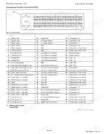
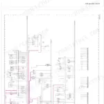
Yes. The Electrical System section holds the electrical circuits for the B2650 and B3350 plus the starting and stopping system, controller, and safety switches. p. 337
Does it cover the DPF and engine controls?
Yes. The Engine section covers the engine body, the engine control system and electronic governor for the V1505-T-E4, and the exhaust aftertreatment and DPF. p. 79
Does it list wheel torque specs?
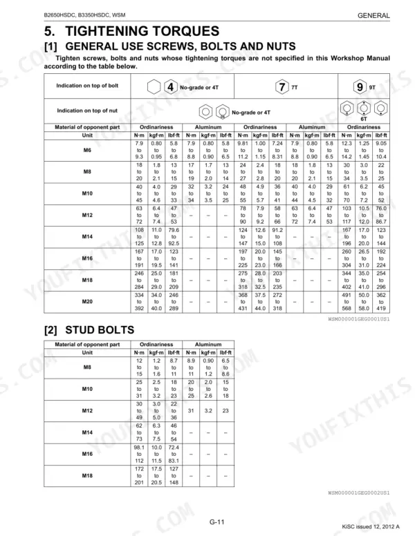
Yes. Tightening torque tables are in the General section, and the rear and front wheel nut and bolt torque values are given with the tractor's checking procedures. p. 15
How quickly can I access this Kubota B2650HSDC manual after buying?
A 470-page searchable PDF downloads the moment you check out. Open it on a laptop, tablet, or phone and take it straight to the shop floor.
Can I print specific sections of this manual?
Yes. Print individual pages or full chapters for your own shop use, on letter or A4 paper.
Does this Kubota B2650HSDC manual show the machine's wiring?
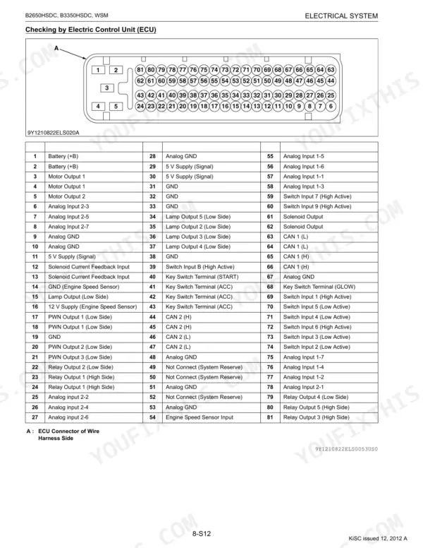
Yes, this Kubota B2650HSDC, B3350HSDC Workshop Manual includes complete electrical wiring diagrams, wire routing, and connector pinouts.





Reviews
There are no reviews yet.