Part of the Kubota Repair Manuals.
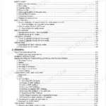
This Kubota Service Manual covers the R310(B) and R410(B) wheel loaders, powered by the V1305-RP and V1902-BDW-3 diesel engines. Running 448 pages, it is the factory service documentation, organised into eleven sections that move from safety precautions and general specifications through the power train, brake system, steering, front shovel loader, backhoe, structure, engine, and electrical system.
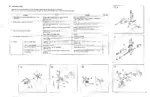
The manual carries Kubota's own testing, adjustment, and servicing procedures for each system: reduction gear case and differential work in the power train, relief pressures and pump flow in the steering, negative brake and parking brake checks, engine performance curves and tightening torques, and full electrical circuit diagrams. Owners and independent mechanics can use it to diagnose faults, set pressures, overhaul components, and return the loader to specification rather than guessing.
It is delivered as a searchable, printable PDF download.
What's Inside This Manual
| System | Pages | Key Topics |
|---|---|---|
| Precautions | Safety Precautions for Servicing, Disassembling and Reassembling, Checks and Maintenance, Safety Levers and Appliances | |
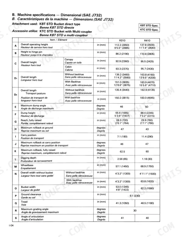
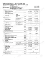
| Section I: General | Body, Engine and Backhoe Serial Numbers, Machine Specifications (Dimensional, Operational, Systematical), Routine Check Chart, Periodical Check and Maintenance Chart | |
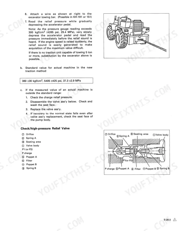
| Section Ii: A-Lst System | Service Information (Traction Procedure), Specifications | |
| Section Iii: Power Train | Specification, Servicing (Reduction Gear Case, Differential Axle, Propeller Shaft) | |
| Section Iv: Brake System | Specification, Testing & Adjustment (Pedal Stroke, Negative Brake Function, Braking Distance, Parking Brake Capacity) | |
| Section V: Steering System | Specification, Testing & Adjustment (Main Relief Pressure, Overload Relief Pressure, Main Pump Flow Rate, Steering Wheel, Hoses and Fitting Installation) | |
| Section Vi: Front Shovel Loader | Specifications | |
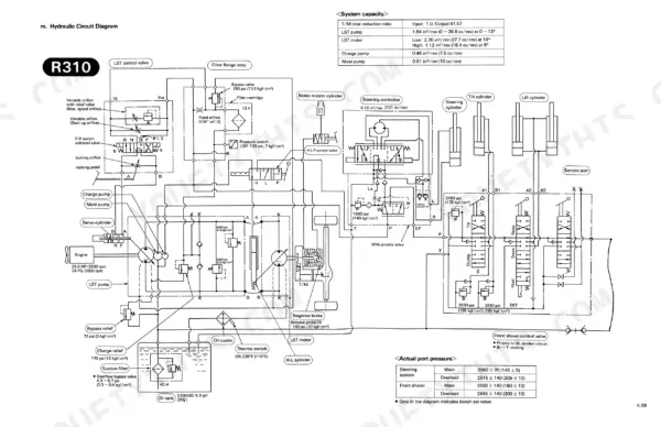
| Section Vii: Backhoe | Mechanism (Oil Flow Chart, Hydraulic Circuit Diagram), Routine Maintenance | |
| Section Viii: Structure | Specification (Center Pin & Bushing), Testing & Adjustment (Center Pin & Bushing Play), Servicing (Center Pin & Shaft, Hood, Rops/Fops Cab) | |
| Section Ix: Engine | Engine Performance Curve, Maintenance Standard, Tightening Torque, Service Information, Specification, Testing & Adjustment | |
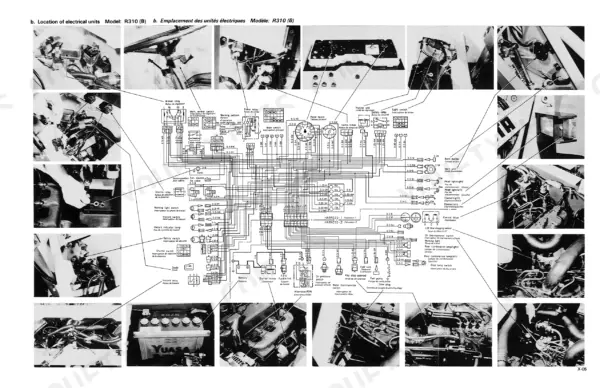
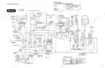
| Section X: Electrical | Data of Electrical Units, Location of Electrical Units, Electrical Circuit Diagram, Comparison of Electrical Wiring, Wire Harness Clamp Location | |
| Section Xi: Optional Units & Attachments | List of Optional Unit & Attachment, Limited Slip Differential (Lsd) |
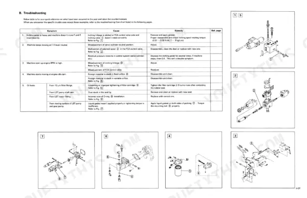
Every system also includes troubleshooting.
Quick Reference Specifications
| Specification | Value | Page |
|---|---|---|
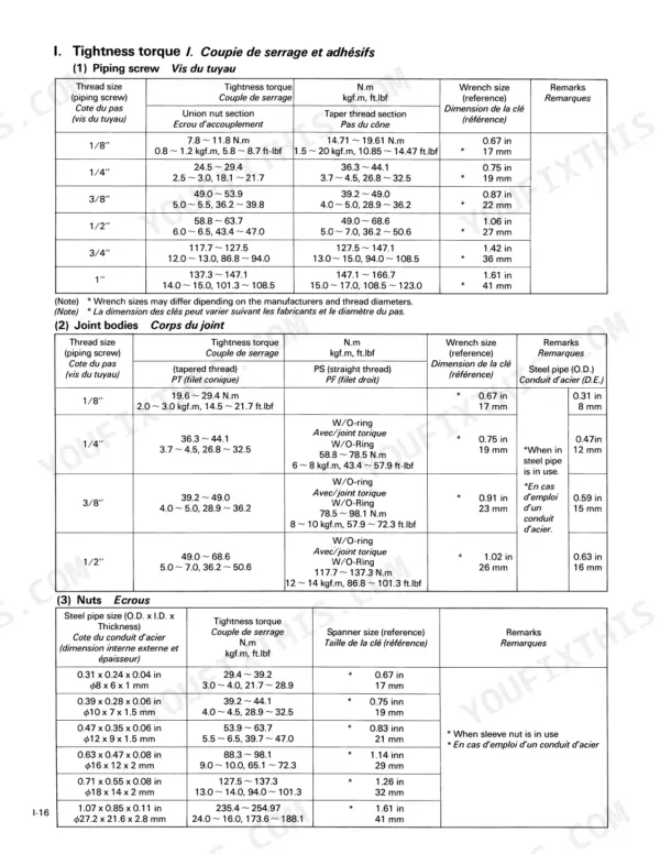
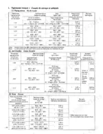
| Piping screw torque (1/8") | 7.8 – 11.8 N.m (5.8 – 8.7 ft.lbf, 0.8 – 1.2 kgf.m) | p. 29 |
| Piping screw torque (1/4") | 24.5 – 29.4 N.m (18.1 – 21.7 ft.lbf, 2.5 – 3.0 kgf.m) | p. 29 |