




This is the Kubota KX040-4 mini-excavator Workshop Manual, a 450-page reference for machines powered by the D1803-CR-TE4-BH1 and D1803-CR-TE4-BH2 common-rail diesel. It is delivered as a downloadable PDF you can open on a phone, tablet or computer, or print for the workshop.
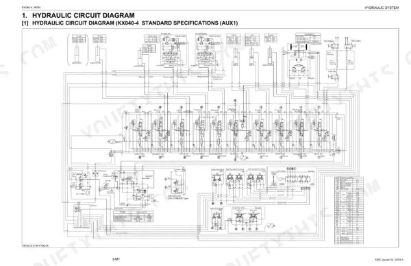
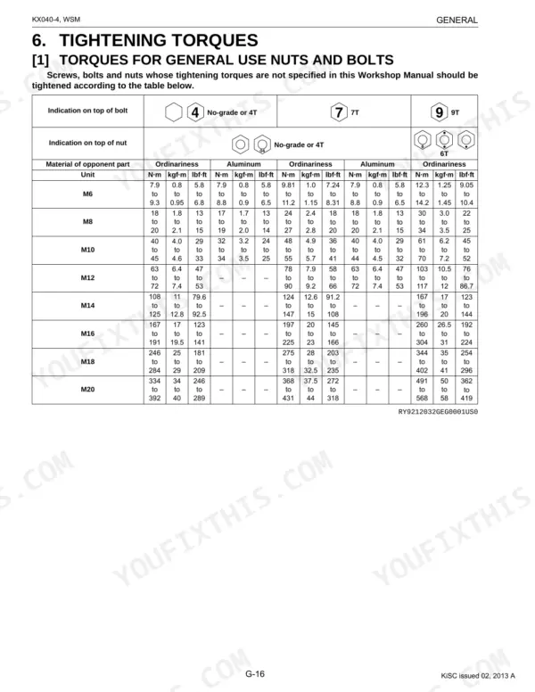
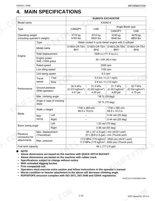
Coverage is built around the machine itself: machine body and front boom work, the large hydraulic system with pump and control valve detail, the electrical system with full wiring circuits, and the cabin and air conditioning. You also get identification procedures, tightening torques, oil and water capacities, maintenance intervals, an electrical circuit diagram, and a connector chart.
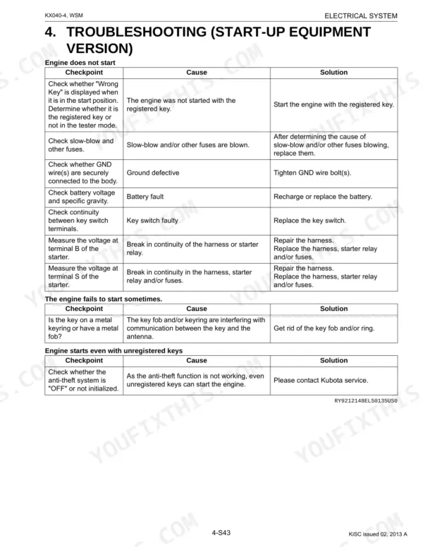
With it you can chase a no-start or sudden shutdown, restore lost hydraulic response, set rubber track tension, service the air conditioning, and work through Kubota's own troubleshooting tables for slow or dead actuators.
Complete the set for your KX040-4
- Operator Manual: Kubota KX040-4 Excavator Operator Manual
What's Inside This Manual
| System | Pages | Key Topics |
|---|---|---|
| G General | Checking Excavator Identification, Engine Identification (Model Name and Serial Number, Cylinder Number), Muffler Full Assembly Identification (Part Number and Serial Number) | |
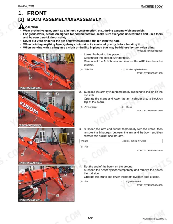
| Machine Body | Front (Boom Assembly/Disassembly, Table of Dimensions) | |
| Engine | Specifications, Dimensions, Performance Curves | |
| Hydraulic System | Hydraulic Circuit Diagram, Pump (Specifications, Function and Structure), Control Valves (Specifications | |
| Electrical System | Electrical Device Layout and Wiring Circuit (Precautions on: How to Clamp the Electrical Wiring, Handling Electrical Connectors) | |
| Cabin | Air Conditioning System (Structure, How the Mechanisms of the System Work, Compressor, Air Conditioning Unit, Condenser, Receiver, Pressure Switch, Electrical System) | |
| Electrical Circuit Diagram | Relay Starter, Relay, Solenoid Lever Lock, Alternator Assy, Injector Assy, Wire Ass, Solenoid, Buzzer Back | |
| Connector Chart | A/C Heater, Blower Motor, Alternator, Battery, Engine Control Unit (ECU), Fuel Pump, Injector, Starter |
Quick Reference Specifications
| Specification | Value | Page |
|---|---|---|
| Rubber Track Tension | 10 to 15 mm | p. 74 |
| ECU (+B) Fuse Capacity | 10A | p. 325 |
| Temperature Sensor Operating Range (OFF) | 153 to 163 °C | p. 389 |
| Temperature Sensor Operating Range (ON) | 120 ± 5 °C | p. 389 |
| AC Drive Belt Tension (Deflection) | 12 to 15mm (0.47 to 0.59 in.) when 68.6N (7.0 kgf, 15.4 lbf) of forced is applied | p. 407 |
| Coolant Capacity (Canopy) | 6.7 L (1.8 U.S.gals) | p. 41 |
| Coolant Capacity (Cabin) | 7.0 L (1.8 U.S.gals) | p. 41 |
| Fuel Filter Cartridge Replacement Interval | Every 500 hrs | p. 42 |
| Radiator Hoses and Clamps Check Interval | Every 200 hrs | p. 42 |
| Radiator Hoses and Clamps Replace Interval | Every 2 years | p. 42 |
| Hydraulic Return Filter Element Replacement Interval | Every 1000 hrs | p. 42 |
