


Part of the Kubota Repair Manuals.
This Kubota L45, TL1000A, BT1000A Workshop Manual (OEM #9Y111-02670) treats the tractor, TL1000A front loader, and BT1000A backhoe as one factory-integrated system across 589 pages. Wiring diagrams trace the ECU and Intellipanel control circuits, while hydraulic schematics follow every fluid path through the HST transmission and the loader circuits. Exploded views, error code charts for the electronic controls, 11 troubleshooting procedures, and torque tables back up step-by-step disassembly and rebuild work that runs from engine to rear axle. When you button everything back up, the rear wheel mounting hardware takes 196 N·m (145 lbf·ft) and the 1/4-inch hydraulic fittings want 22.6 to 27.5 N·m before you call it done. Three machines, one reference, every spec searchable by keyword on whatever device happens to be in the shop.
What's Inside This Kubota L45, TL1000A, BT1000A Manual
| System | Pages | Key Topics |
|---|---|---|
| G General | - | Tractor Identification (Model Name and Serial Numbers, Cylinder Number), Handling Precautions for Electrical Parts and Wiring (Battery, Fuse, Connector, Handling of Circuit Tester) |
| P Preparation | - | Disassembling and Assembling (Dismounting Front Loader Assembly, Separating Canopy, Separating ROPS and Frame, Separating Tractor Frame) |
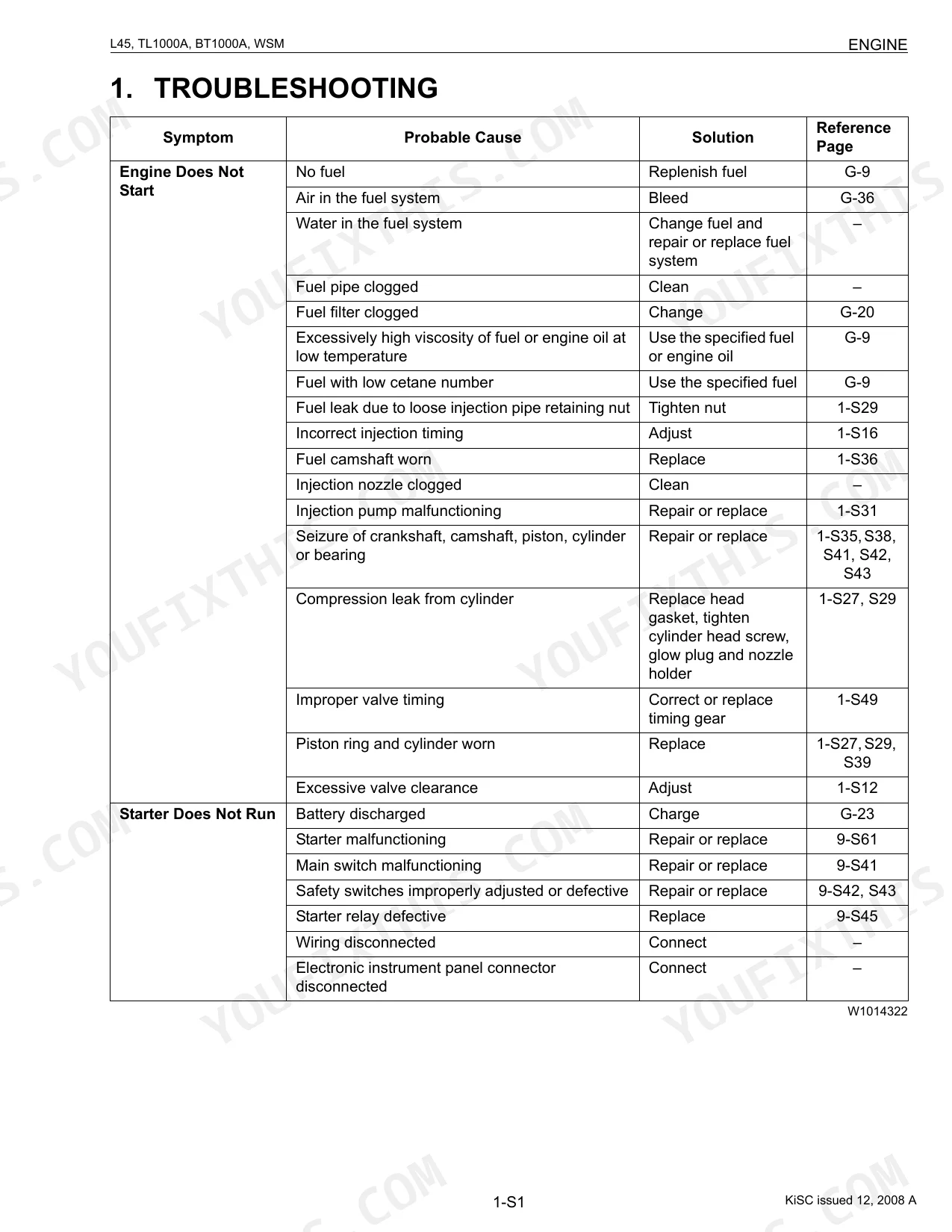
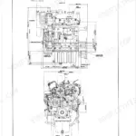
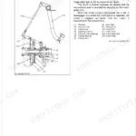
| Engine | - | Features, Servicing Specifications, Checking, Disassembling and Servicing (Checking and Adjusting, Preparation, Disassembling and Assembling) |
| Clutch | - | Feature, PTO System (Structure, PTO Clutch), Checking and Adjusting (Clutch Pedal, PTO Clutch Valve), Servicing (Traveling Clutch |
| Transmission | - | Hydrostatic Transmission (Power Train, Shift Linkage Mechanism, Auto Throttle Advance, Crawl Control), Checking |
| Rear Axle | - | Structure, Disassembling and Assembling (Preparation) |
| Brakes | - | Linkage, Rear Parking Brake Linkage, Operation, Checking and Adjusting (Check and Adjusting), Servicing (Brake: Pedal, Case), Disassembling and Assembling (Brake: Pedal |
| Front Axle | - | Servicing Specifications, Structure, Checking and Adjusting, Servicing (Differential Gear and Spiral Bevel Pinion, Bevel Gears, Front Axle Case, Bevel Gear Case) |
| Steering | - | Hydraulic Circuit, Structure, Checking and Adjusting (Steering Controller, Hydraulic Pump) |
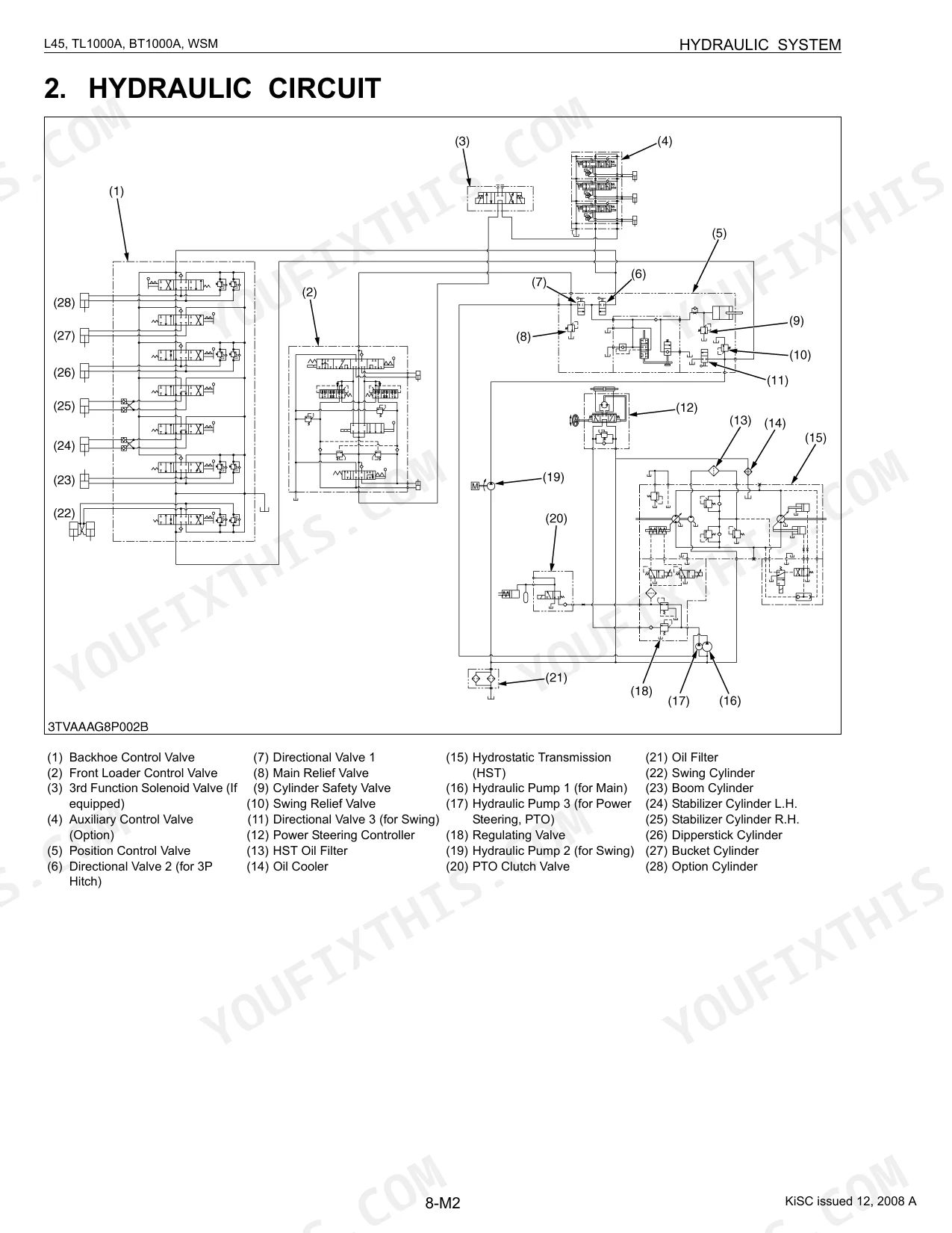
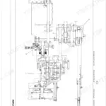
| Hydraulic System | - | Function of Component Parts (Position Control Linkage, Directional Valve, Relief Valve, Hydraulic Cylinder), Others (Control Valve, Cylinder Safety Value, Regulating Valve) |
| Electrical System | - | Wiring Diagram, Electronic Control Panel (System Outline and Electrical Circuit, Construction and Function of Components, Basic Control System, Assistant Control System) |
| Front Loader | - | Hydraulic System (Structure, Operation, Overload Relief Valve, Boom Cylinder and Bucket Cylinder, 3rd. Function Solenoid Valve), Dismounting and Mounting (Front Loader Assembly) |
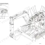
| Backhoe | - | Backhoe Terminology, Specifications (Dimensions, Digging Force, Cycle Time, Hydraulic Cylinders, Bucket Size, Lift Capacity) |
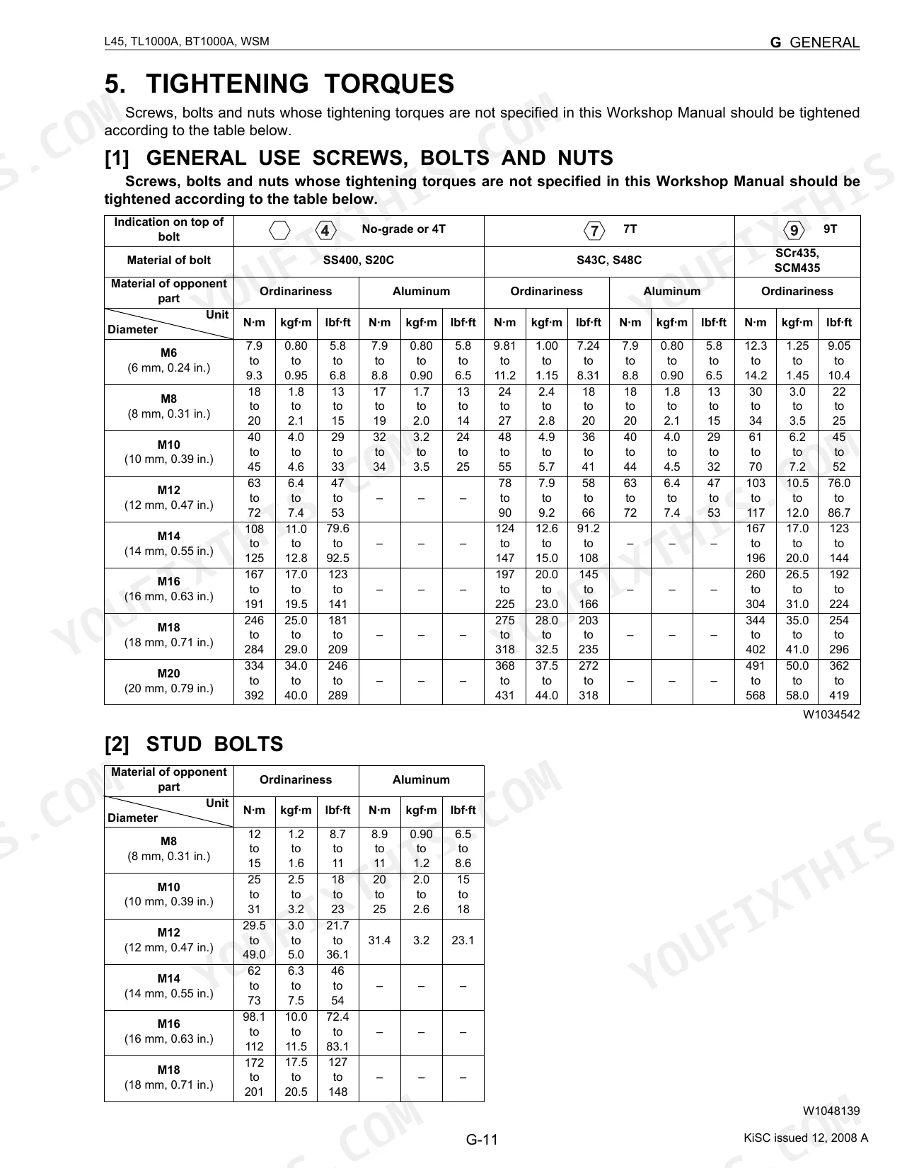
Every system also includes tightening torques.
Quick Reference Specifications
| Specification | Value | Page |
|---|---|---|
| L45 | ||
| Front wheel mounting screw and nut torque | 185 N·m (19 kgf·m, 136 lbf·ft) | p. 37 |
| Rear wheel mounting screw and nut torque | 196 N·m (20 kgf·m, 145 lbf·ft) | p. 37 |
| All Models | ||
| Hose size 02 (1/8) hydraulic fitting torque | 13.7 to 15.7 N·m (1.4 to 1.6 kgf·m, 10.1 to 11.6 lbf·ft) | p. 30 |
| Hose size 03, 04 (1/4) hydraulic fitting torque | 22.6 to 27.5 N·m (2.3 to 2.8 kgf·m, 16.6 to 20.3 lbf·ft) | p. 30 |
| Fuel filter element replacement interval | every 400 Hr | p. 31 |
| Engine oil filter replacement interval | every 200 Hr | p. 31 |
| Fuel filter element clean interval | every 100 Hr | p. 31 |
| TL1000A | ||
| Hydraulic hose retaining nut (3/4) torque (Front Loader) | 35 to 41 N·m (3.6 to 4.1 kgf·m, 26 to 30 lbf·ft) | p. 510 |
| BT1000A | ||
| Hydraulic hose to swing cylinder retaining nut (9/16) torque (Backhoe) | 22 to 25 N·m (2.3 to 2.5 kgf·m, 16 to 19 lbf·ft) | p. 565 |
| Swing cylinder trunnion boss and cylinder support bushing clearance | 0.090 to 0.17 mm (0.0036 to 0.0066 in.) | p. 585 |
| Main frame fulcrum pin and bushing clearance | 0.16 to 0.23 mm (0.0063 to 0.0090 in.) | p. 585 |
Kubota L45, TL1000A, BT1000A Common Problems This Manual Covers
Kubota L45 TL1000A loader bucket dumps slowly while other loader functions operate at normal speed.
Inspect the bucket cylinder tube and seals for damage, then check the piston rod for straightness. Replace the rod if the bend exceeds the allowable limit of 0.25 mm (0.0098 in.) shown on page 506. Confirm the pin to bucket cylinder rod end bushing clearance sits within 0.20 to 0.48 mm.
Manual Section: Front Loader Troubleshooting p. 504Engine temperature gauge moves into the red zone or machine shuts down from high heat.
Check the radiator and cooling system for blockages. Look at the coolant recovery tank on page 27 and top it up to the proper level. Keep the total recovery tank capacity at or below 1 L (1.1 U.S.qts, 0.88 Imp.qts). Clear any debris from the cooling path, then restart the engine.
Manual Section: Engine TroubleshootingVisible fluid leaks from the backhoe swing cylinder hoses during daily walk-around inspection.
Examine the hydraulic connections at the swing cylinder. Torque the 9/16 hydraulic hose retaining nut to 22 to 25 N·m (16 to 19 lbf·ft) per page 565. Measure the swing cylinder trunnion boss and support bushing clearance; it should fall between 0.090 to 0.17 mm.
Manual Section: Backhoe TroubleshootingFront wheels wander or vibrate excessively during transport or while driving on hard surfaces.
Verify the condition of the front tires and rims. Torque the front wheel mounting screws and nuts to 185 N·m (136 lbf·ft) as detailed on page 37. Check the axle case oil level against its 7.0 L (7.4 U.S.qts) capacity, referenced on page 12.
Manual Section: Front Axle TroubleshootingFrequently Asked Questions
How do I reset the Kubota L45 error code?
To reset an error code on the Kubota L45, open Mode "D" (Error Information Reset Mode) on the electronic instrument panel. Once you select it, "CLEAR" and "PUSH SW" appear for two seconds. Then hold down the display mode switch for more than 2 seconds, and the error information is deleted. p. 406
What does the Kubota L45 warning light mean?
The Kubota L45 warning light blinks to indicate specific error codes, such as ERROR-00 (Electronic meter in trouble), ERROR-20 (Communication error), ERROR-30 (ECU in trouble), and ERROR-40 (Power supply of sensor from ECU in trouble). It also blinks for various sensor failures like HST pedal sensor (ERROR-81) or throttle sensor (ERROR-84). p. 375
How do I clear the Kubota L45 hydraulic fault code?
The L45 uses one reset path for hydraulic fault codes and every other code. Reach Mode "D" (Error Information Reset Mode) on the electronic instrument panel, wait for "CLEAR" and "PUSH SW" to show for two seconds, then hold the display mode switch for more than 2 seconds. The stored fault clears. p. 406
How do I reset the Kubota TL1000A monitor after service?
Resetting the Kubota TL1000A monitor after service clears the "SERVICE INSPECT" message. With the hour meter (Normal Display 1) showing, keep pushing both the display mode switch (2) and travel speed switch (3) for two seconds or more. p. 373
Is this Kubota L45, TL1000A, BT1000A Workshop Manual a digital download?
This is a 589-page searchable PDF ready for immediate download. It works on any device, so you can pull it up on your phone while you're under the hood. No shipping, no waiting.
Am I able to print pages from this manual?
Yes. The PDF carries no DRM restrictions, so you can print any page or section you need for your shop. It works with any standard printer.
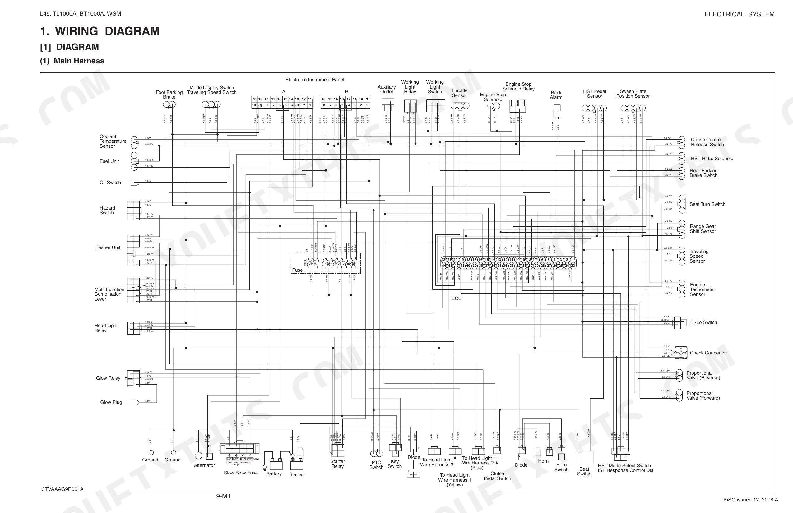
Are electrical wiring diagrams included in this Kubota L45, TL1000A, BT1000A?
Yes, this Kubota L45, TL1000A, BT1000A Workshop Manual includes complete electrical wiring diagrams, wire routing, and connector pinouts.


Reviews
There are no reviews yet.