


Part of the Kubota Repair Manuals.
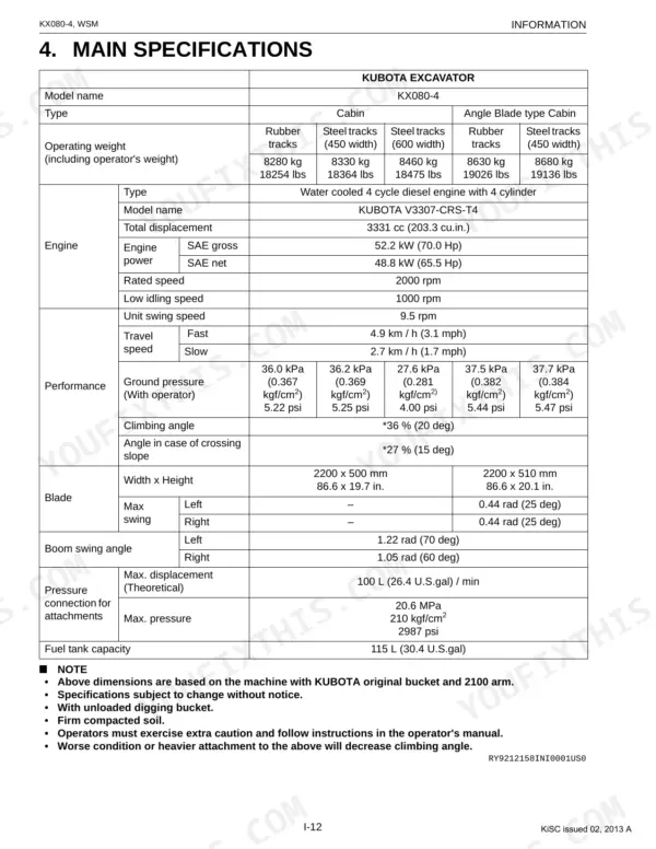
This is the Kubota factory Service Manual for the KX080-4 compact excavator, built around the V3307-CRS-T4 diesel engine. It runs 490 pages and is organized into General, Mechanism, and Servicing coverage, with detailed bookmarks for fast navigation.
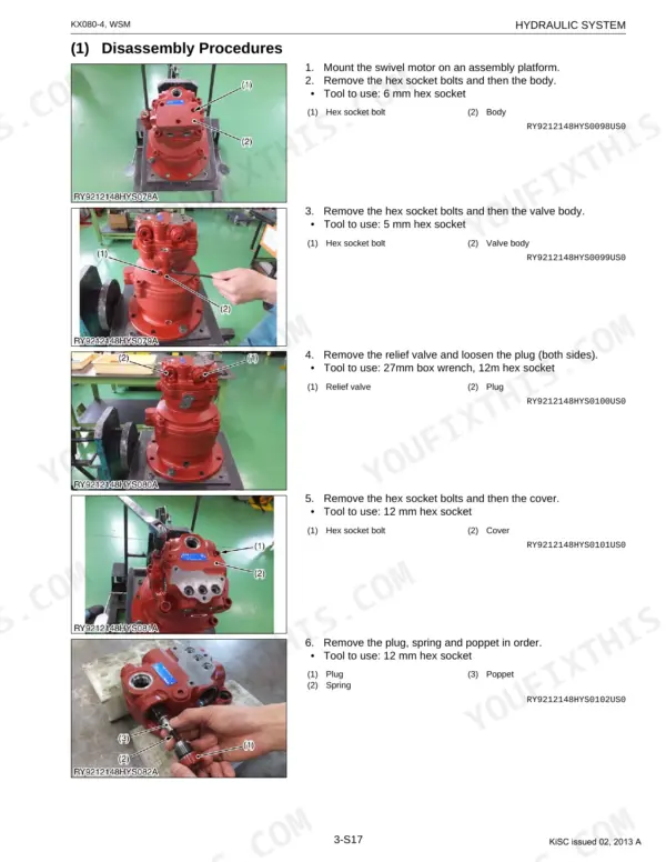
The manual works through machine-body and undercarriage service, the engine, the full hydraulic system including pumps, control valve, swivel and travel motors, cylinders, and pilot valves, the electrical system, and the cabin with its air conditioning. It closes with the electrical circuit diagram and a connector chart for wiring work.
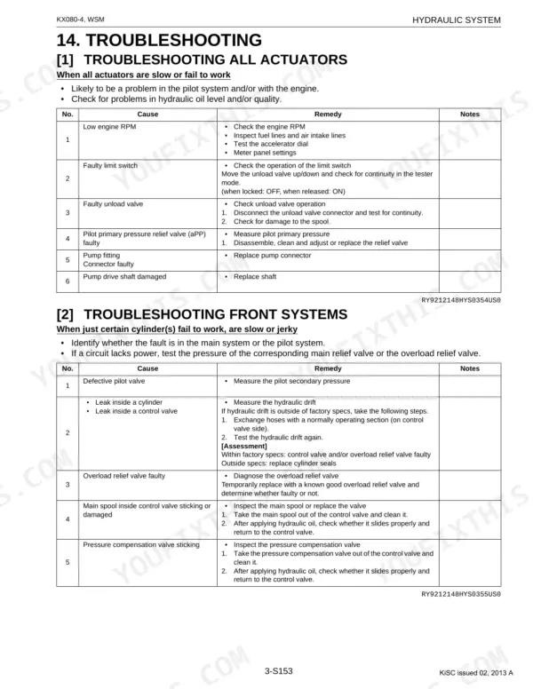
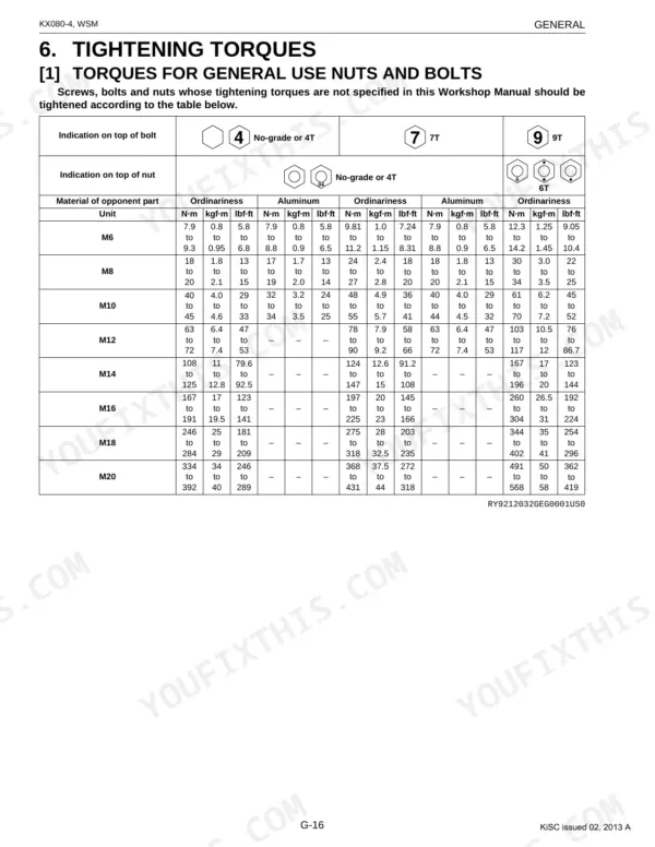
Use it to trace overheating and hydraulic power loss during digging, weak or jerky travel, a boom or bucket that drifts, engine stalling under load, or electrical warning lights, using factory troubleshooting, performance standards, and tightening torques. It is delivered as a downloadable, printable PDF you can keep in the cab or on the bench.
What's Inside This Manual
| System | Pages | Key Topics |
|---|---|---|
| G General | Contents, Checking Excavator Identification, Engine Identification (Model Name and Serial Number, Cylinder Number) | |
| Machine Body | Contents, Front (Boom Assembly/Disassembly, Table of Dimensions, Bucket, Pin, Bushings, Arm, Blade) | |
| Engine | General, Specifications, Dimensions, Performance Curves, Fan Drive | |
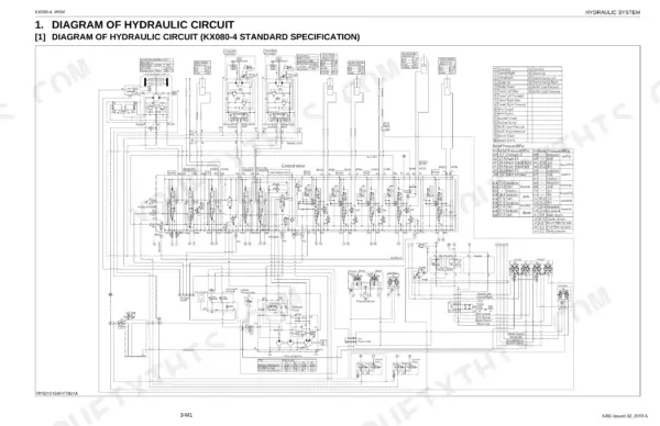
| Hydraulic System | Contents, Diagram of Hydraulic Circuit, Hydraulic Device Layout | |
| Electrical System | Contents, Layout of Electrical Devices and Wiring Routing (Precautions on How to Clamp the Electrical Wiring, Precautions on Handling Electrical Connectors) | |
| Cabin | Air Conditioning System, Structure, How the Mechanisms of the System Work, Compressor, Air Conditioning Unit, Condenser, Receiver, Pressure Switch | |
| Electrical Circuit Diagram | Composition Specification Code Notes, Engine Control Unit and Sensors, Relays and Solenoids, Fuses and Power Distribution, Operator Controls and Indicators | |
| Connector Chart | Engine Control Unit Connectors, Sensor Connectors, Actuator and Solenoid Connectors, Power Distribution Connectors, Operator Interface Connectors |
Documents This Manual Refers To
The manufacturer cites these publications by number. We carry them:
Quick Reference Specifications
| Specification | Value | Page |
|---|---|---|
| Track roller mounting bolts | 166.7 to 196.1 N·m, 17.0 to 20.0 kgf·m, 123.0 to 144.6 lbf·ft | p. 80 |
| Swivel bearing tightening torque | 259.9 to 304.0 N·m, 26.5 to 31.0 kgf·m, 191.7 to 224.2 lbf·ft | p. 68 |
| Hydraulic return filter cartridge replacement interval | replace every 500 hrs | p. 41 |
| Filter in the pilot hydraulic system replacement interval | replace every 1000 hrs | p. 41 |
| Fuel filter cartridge replacement interval | replace every 500 hrs | p. 41 |
| Air filter element Outer element clean interval | clean every 200 hrs | p. 41 |
| Air filter element Outer element replacement interval | replace every 1000 hrs | p. 41 |
| Pilot filter replacement interval | replace every 1000 hrs | p. 41 |
| Track Rollers O.D. (Factory spec) | 132 mm | p. 83 |
| Track Rollers O.D. (Recommended replacement values) | 124 mm | p. 83 |
| Front Idler O.D. (Factory spec) | 390 mm | p. 83 |
| Front Idler O.D. (Recommended replacement values) | 384 mm | p. 83 |