


Part of the Kubota Repair Manuals.
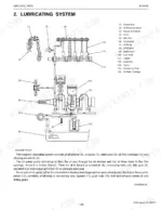
This is the full Kubota workshop service manual for the GR2100EC lawn and garden tractor, powered by the D782-E2-GX three-cylinder diesel (publication 9Y011-15412). Its 299 pages are organized into General, Engine, Transaxle, Brakes, Front Axle, Steering, Hydraulic System, Electrical System, and Mower sections, each with mechanism description and step-by-step servicing.
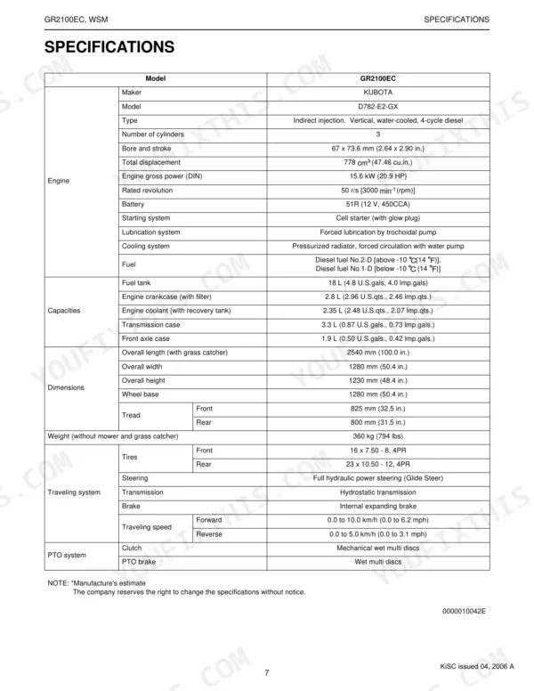
Mechanics can use it to rebuild the hydrostatic transaxle, service the diesel engine, diagnose the Glide Steer drive, troubleshoot the PTO and electrical circuits, and set the hydraulic relief valves. It carries factory specifications and allowable limits, tightening torques, wiring diagrams, fuse ratings, and switch resistance values so repairs are made to spec.
Delivered as an instantly downloadable PDF you can read on any device or print the pages you need.
What's Inside This Kubota GR2100EC Manual
| System | Pages | Key Topics |
|---|---|---|
| G General | Identification, Handling Precautions for Electrical Parts and Wiring (Battery, Fuse, Connector, Handling of Circuit Tester), Lubricants, Fuel and Coolant, Maintenance Check List | |
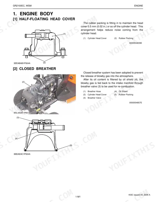
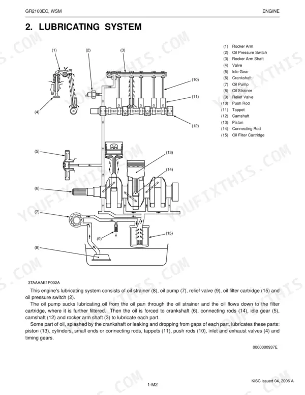
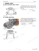
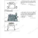
| Engine | Engine Body (Half-Floating Head Cover, Closed Breather), Lubricating System, Cooling System, Fuel System (Fuel Line), Servicing Specifications | |
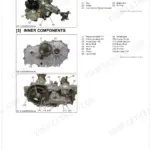
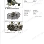
| Transaxle | Travelling System (Hydrostatic Transmission, Structure, Oil Flow, Operation, By-Pass Valve, Control Linkage, Glide Steer Section, General, Front Wheel Drive Section) | |
| Brakes | Servicing Specifications, Disassembling and Servicing (Checking and Adjusting, Disassembling and Assembling, Pedal System Component, Brake Assembly) | |
| Front Axle | Structure, Servicing Specifications | |
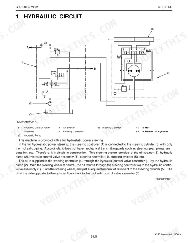
| Steering | Steering Controller, Steering Cylinder, Hydraulic Circuit, Servicing Specifications | |
| Hydraulic System | Hydraulic Pump, Hydraulic Control Valve (Mower Lift Circuit, HST Relief Valve), Mower Lift Cylinder, Mower Linkage, Hydraulic Circuit, Servicing Specifications | |
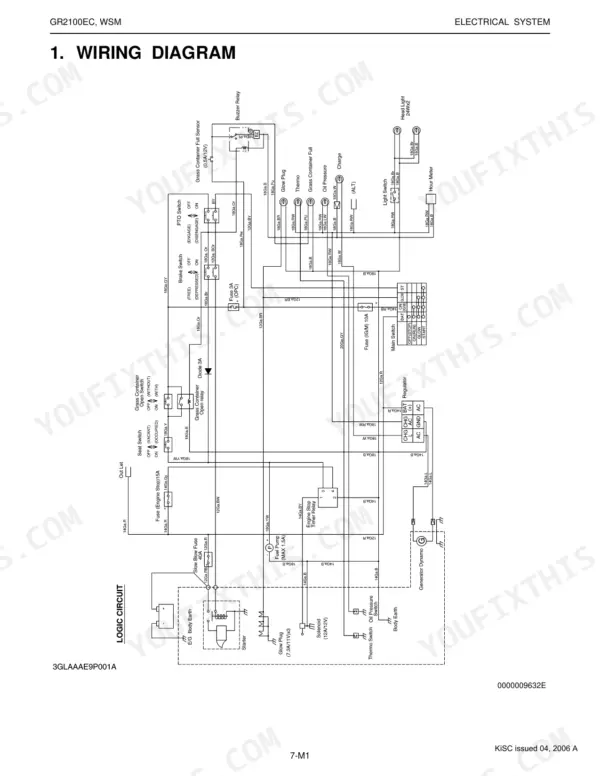
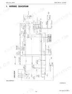
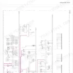
| Electrical System | Wiring Diagram, Starting System, Charging System, Lighting System, Servicing Specifications | |
| Mower | Power Transmission, Lifting Mechanism |
Every system also includes tightening torques, checking, and troubleshooting.
Quick Reference Specifications
| Specification | Value | Page |
|---|---|---|
| General Use Screws, Bolt and Nuts (M6 Ordinariness) | 7.85 to 9.31 N-m | p. 22 |
| General Use Screws, Bolt and Nuts (M8 Ordinariness) | 17.7 to 20.5 N-m | p. 22 |
| Glide Steer wire length 'A' | 10 to 12 mm | p. 162 |
| Length of the steering cylinder tube (L1) | 79.6 to 94.0 mm | p. 197 |
| Fuse E/G STOP (a) capacity | 15 A | p. 51 |
| Fuse IG/M (b) capacity | 10 A | p. 51 |
| Fuel Pump Connector Voltage (Between connector terminals) | Approx. battery voltage | p. 270 |
| Battery type | 51R (12 V, 450CCA) | p. 9 |
| Battery Voltage (Factory spec) | More than 12 V | p. 262 |
| PTO Switch Resistance (between terminal a and b) when plunger is pushed | 0 Ω | p. 268 |
| PTO Switch Resistance (between terminal a and b) when plunger is released | Infinity | p. 268 |
| PTO Clutch Disc Thickness (Factory spec) | 1.3 to 1.5 mm | p. 150 |
Kubota GR2100EC Common Problems This Manual Covers
Blade PTO will not engage
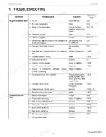
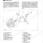
A dead PTO usually comes back to a safety interlock, blown fuse, faulty switch, or wiring fault in the PTO circuit. The electrical section gives the PTO switch resistance checks, showing 0 ohms when the plunger is pushed and infinity when released.
Manual Section: 7 Electrical System p. 251Glide Steer drive loss or broken cables
Front axle cables tied to the Glide Steer system can break or slip, causing intermittent loss of drive. The transaxle section covers the Glide Steer mechanism, cable settings, and transaxle disassembly.
Manual Section: 2 Transaxle p. 129Weak or erratic hydraulic lift
Slow or inconsistent mower lift can trace to relief valve settings, the pump, or the control valve. The hydraulic section gives the main relief valve pressure of 9.5 to 11.0 MPa and full servicing steps.
Manual Section: 6 Hydraulic System p. 226Steering wander or excess wheel play
Loose or worn steering shows up as wander and excess free play. The steering section covers the controller and cylinder and lists a steering wheel play spec of 30 to 70 mm.
Manual Section: 5 Steering p. 208Hard starting or diesel fuel faults
Hard starting often points to the fuel system, injection nozzles, or compression. The engine section covers the fuel line, servicing specifications, and disassembly of the D782 diesel.
Manual Section: 1 Engine p. 65Brake drag or long pedal travel
Excessive pedal travel or dragging brakes need adjustment or overhaul. The brakes section gives the pedal free travel spec of 15 to 25 mm and the checking and adjusting procedure.
Manual Section: 3 Brakes p. 179Frequently Asked Questions
Which machine and engine does this manual cover?
It is the workshop service manual for the Kubota GR2100EC lawn and garden tractor, powered by the D782-E2-GX three-cylinder indirect-injection diesel, publication 9Y011-15412.
Where are the torque specifications?
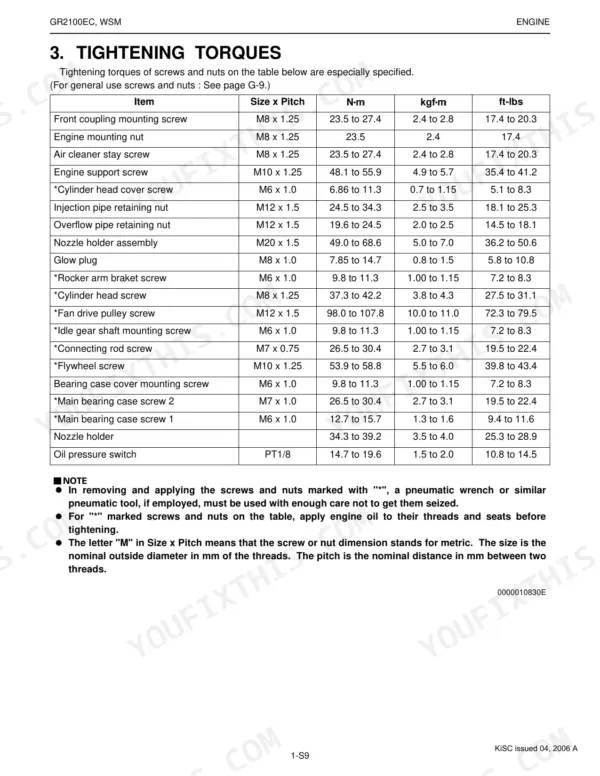
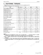
The General section carries the tightening torque tables, for example 7.85 to 9.31 N-m for an M6 general-use bolt and 17.7 to 20.5 N-m for an M8, plus component-specific torques throughout each section. p. 22
Does it list fuse ratings and electrical values?
Yes. The manual lists fuse capacities such as 15 A for the E/G STOP fuse, 10 A for IG/M, 3 A for OPC, and a 40 A slow blow fuse, along with wiring diagrams and switch resistance values. p. 51
Does it cover the hydrostatic transaxle rebuild?
Yes. The transaxle section covers the hydrostatic transmission structure, oil flow, by-pass valve, Glide Steer, and front wheel drive, with servicing specifications and clutch disc and spring limits. p. 129
How will I receive this Kubota GR2100EC Workshop Manual?
A 299-page Workshop Manual in searchable PDF format (11 MB), available the moment you complete checkout. View on computer, tablet, or phone, with no shipping wait.
Can I print pages of this Kubota GR2100EC manual for my own shop?
Yes. Print individual pages or full chapters for your own shop use, on letter or A4 paper.
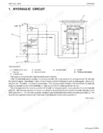
Are hydraulic system diagrams in this Kubota GR2100EC Workshop Manual?
Yes, this Kubota GR2100EC Workshop Manual includes hydraulic system diagrams, circuit schematics, and component specifications.





Reviews
There are no reviews yet.