




This is the factory Kubota Service Manual for the ZD1011-AU zero turn mower, a 293-page document (publication 9Y111-13704) built around the D782-E4 diesel engine. It covers the whole machine, from the engine and transaxle to the mower deck and electrical system.
The manual runs from Information and General through the Engine, Transaxle, Front Axle, Hydraulic System, Electrical System, and the Mower itself. Each section carries mechanism explanations, servicing specifications, troubleshooting, tightening torques, and disassembly and assembly procedures.
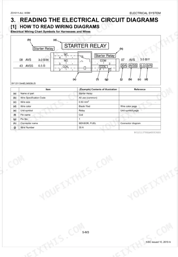
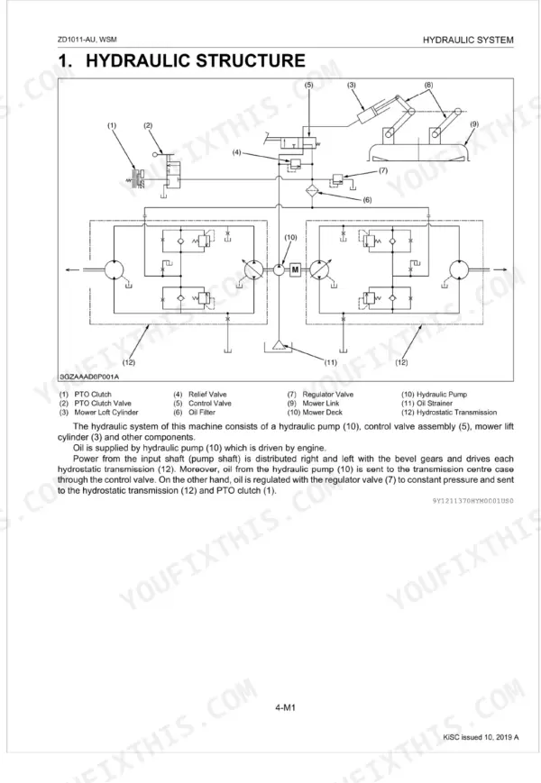
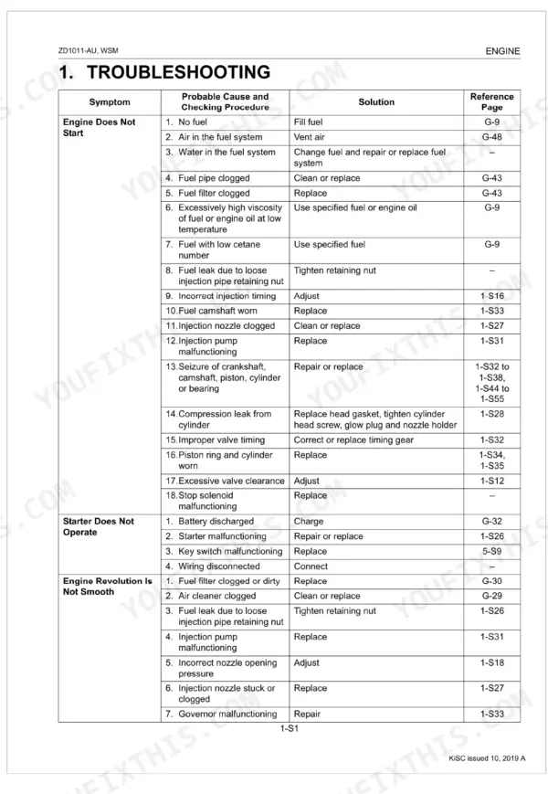
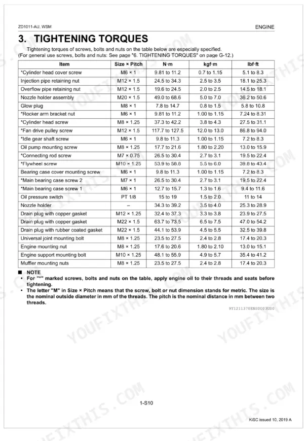
With it an owner or independent mechanic can diagnose a hydrostatic drive fault, set valve clearance and injection pressure on the D782-E4, service the mower lift cylinder, adjust the deck and anti scalp rollers, and trace any circuit from the electrical diagram. It is a searchable PDF download with a text layer, ready for use on a laptop, tablet, or phone in the shop.
What's Inside This Manual
| System | Pages | Key Topics |
|---|---|---|
| Record of Revisions | 3 | Updated Maintenance Chart, Added Engine Valve Clearance, Updated Greasing Points, Corrected Errors, Revised the Capacity of the Radiator, Added Information on Fueling and Refueling |
| Information | 4-17 | |
| General | 18-76 | Identification, Cylinder Nymber, Handling Precautions for Electrical Parts and Wiring (Battery, Fuse, Connector, Handling of Circuit Tester, Color of Wiring), Lubricants |
| Engine | 77-153 | Engine Body (Structure, Cylinder Block, Cylinder Head, Half-Floating Head Cover, Closed Breather, Piston, Piston Ring, Connecting Rod, Crankshaft, Camshaft, Fuel Camshaft, Rocker Arm, Flywheel, Timing Gears) |
| Transaxle | 154-198 | Transaxle Structure (Hydrostatic Transmission Section, Oil Flow, Power Transmission Operation, Pump and Motor, Check Valve and High Pressure Relief Valve, Hydrostatic Control Linkage, Final Reduction Gear Section, PTO Section, Parking Brake Section, Bevel Gear Section) |
| Front Axle | 199-207 | Front Axle Structure, Separating Front Wheel and Wheel Bracket, Separating Front Axle Assembly |
| Hydraulic System | 208-225 | Mechanism, Hydraulic Structure, Hydraulic System Components, Mower Lift Cylinder, Oil Filter, Servicing, Troubleshooting, Servicing Specifications |
| Electrical System | 226-271 | Electrical Diagram, Electrical Connector Chart |
| Mower | 272-293 | Rotary Mower (Structure, Power Train Flow, Lifting Mechanism), Troubleshooting, Servicing Specifications, Tightening Torques, Checking and Adjusting (Anti-Scalp Rollers, Level) |
Quick Reference Specifications
| Specification | Value | Page |
|---|---|---|
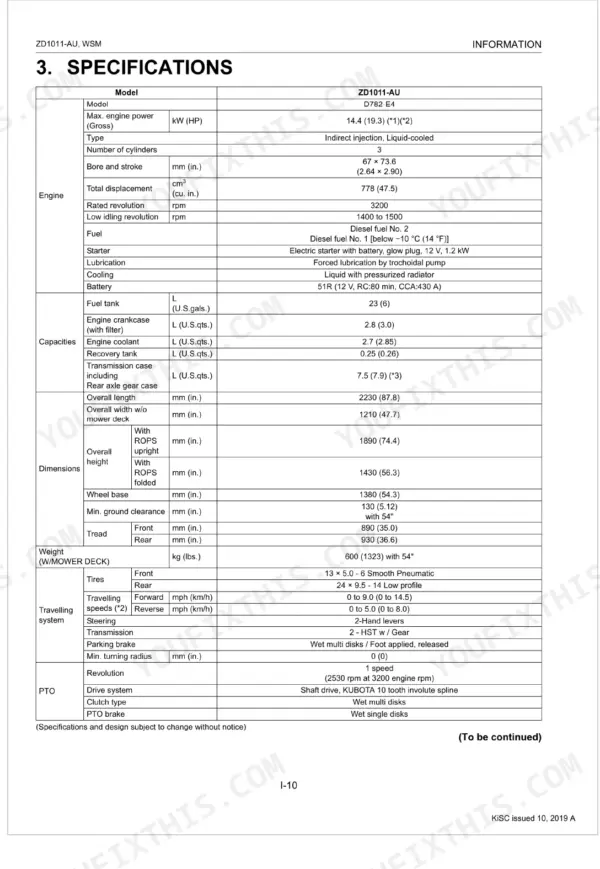
| Fuel tank capacity | 23 L (6.1 U.S.gals. 5.1 Imp.gals.) | p. 28 |
| Engine crankcase (with filter) capacity | 2.8 L (3.0 U.S.qts.) | p. 28 |
| M6 bolt (Ordinariness) | 7.9 to 9.3 N·m | p. 31 |
| M8 bolt (Ordinariness) | 18 to 20 N·m | p. 31 |
| Engine oil change interval | every 200 Hr | p. 33 |
| Engine oil filter replacement interval | every 200 Hr | p. 33 |
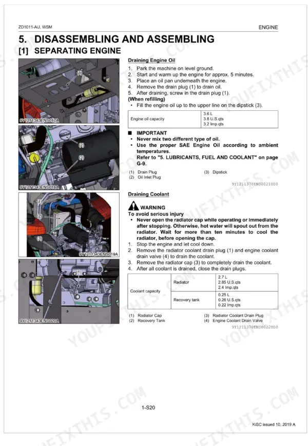
| Engine Oil Capacity (with filter) | 3.6 L | p. 40 |
| Engine Coolant Capacity | 2.7 L | p. 28 |
| Engine Valve Clearance (Cold) | 0.145 to 0.185 mm | p. 29 |
| Engine Compression Pressure | 2.84 to 3.24 MPa | p. 36 |
| Fan Belt Tension (Deflection) | 7.0 to 9.0 mm | p. 38 |
| Radiator Cap Pressure Falling Time | 10 seconds or more | p. 39 |
