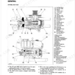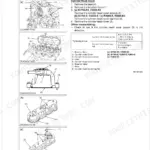



Part of the Kubota Repair Manuals.
This is the factory Kubota Workshop Manual for the RTV1100 utility vehicle, a 521-page service document (publication 9Y121-00111) built around the D1105-E2-UV and D1105-E3-UV diesel engines. It also covers the RTV1100C and includes a dedicated New RTV1100 section at the back.
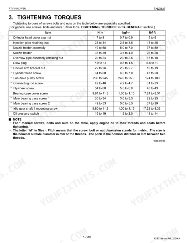
The manual is split into General, Mechanism, and Servicing, with full chapters for the Engine, Transmission, Rear Axle, Brakes, Front Axle, Steering, Hydraulic System, Electrical System, and the air conditioning covered under Others. Each section carries servicing specifications, tightening torques, and disassembly and assembly steps.
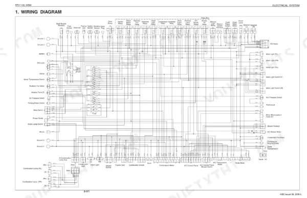
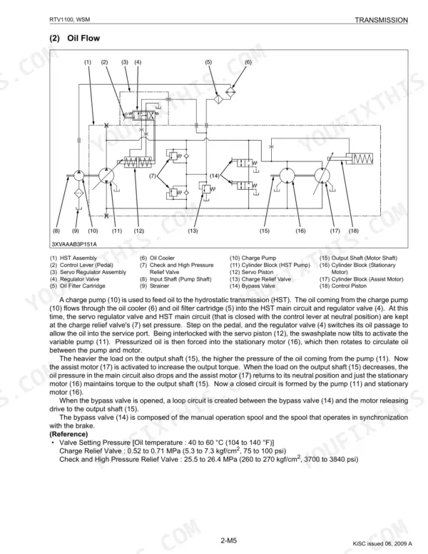
With it an owner or independent shop can rebuild the hydrostatic transmission, set steering and hydraulic relief pressures, service the cab air conditioner, and trace any electrical circuit from the wiring diagram. It is a searchable PDF download with a text layer, ready for a laptop, tablet, or phone in the workshop.
What's Inside This Manual
| System | Pages | Key Topics |
|---|---|---|
| G General | 16-79 | Product Identification, Electrical Parts, Wiring, Lubricants, Fuel, Coolant, Maintenance Check List, Special Tools |
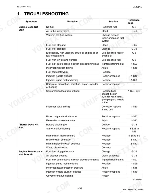
| Engine | 80-137 | Engine Body, Lubricating System, Cooling System, Fuel System, Cylinder Head and Valve, Crankshaft |
| Transmission | 138-215 | Hydrostatic Transmission, Range Gear Shift Section, Front Wheel Drive Section, Front Case, Transmission Case, Differential Gear Assembly |
| Rear Axle | 216-227 | Rear Axle Bracket Assembly, Leaf Spring, Propeller Shaft, Oil Seal, Bearing, Shock Absorber |
| Brakes | 228-254 | Knuckle (Front Brake), Rear Brake, Master Cylinder, Parking Brake, Brake Fluid, Brake Piston |
| Front Axle | 255-283 | Front Suspension, Knuckle Case, Front Differential Case, Strut, Drive Shaft Boot |
| Steering | 284-304 | Hydraulic Circuit, Steering Controller, Steering Cylinder, Relief Valve, Hydraulic Pump |
| Hydraulic System | 305-324 | Hydraulic Circuit, Hydraulic Pump, Hydraulic Cylinder, Hydraulic Control Valve, Relief Valve Setting Pressure |
| Electrical System | 325-383 | Wiring Diagram, Starting System, Charging System, Lighting System, Cooling System, Gauges |
| Others | 384-444 | Compressor, Condenser, Receiver, Air Conditioner Unit, System Control, Air Flow |
| New Rtv1100 | 445-521 | Hydrostatic Transmission (HST), Range Gear Shift Section, Front Wheel Drive Section, Regulator Valve Assembly, Servo Piston |
Quick Reference Specifications
| Specification | Value | Page |
|---|---|---|
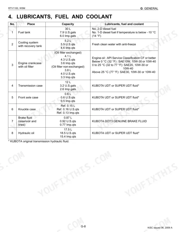
| Engine crankcase (with filter) capacity | 4.1 L (4.3 U.S.qts, 3.6 Imp.qts) | p. 455 |
| Transmission case capacity | 11 L (2.9 U.S.gals, 2.4 Imp.gals) | p. 455 |
| Hydraulic oil capacity | 14.5 L (15.3 U.S.qts, 12.8 Imp.qts) | p. 455 |
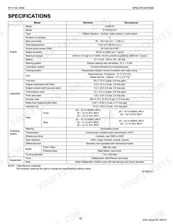
| Fuel tank capacity | 30 L (7.9 U.S.gals, 6.0 Imp.gals) | p. 455 |
| Cooling system with recovery tank capacity | 5.2 L (5.5 U.S.qts, 4.6 Imp.qts) | p. 455 |
| Brake fluid (reservoir and lines) capacity | 0.87 L (0.92 U.S.qts, 0.77 Imp.qts) | p. 455 |
| Knuckle case capacity (one side) | Ref. 0.15 L (Ref. 0.16 U.S.qts, Ref. 0.13 Imp.qts) | p. 455 |
| M6 (6 mm, 0.24 in.) Ordinariness tightening torque | 7.9 to 9.3 N·m (0.80 to 0.95 kgf·m, 5.8 to 6.8 lbf·ft) | p. 27 |
| M8 (8 mm, 0.31 in.) Ordinariness tightening torque | 18 to 20 N·m (1.8 to 2.1 kgf·m, 13 to 15 lbf·ft) | p. 27 |
| M10 (10 mm, 0.39 in.) Ordinariness tightening torque | 40 to 45 N·m (4.0 to 4.6 kgf·m, 29 to 33 lbf·ft) | p. 27 |
| Engine oil change interval | every 50 hours | p. 31 |
| Greasing interval | every 50 hours | p. 31 |