
Part of the Kubota Repair Manuals.
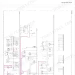
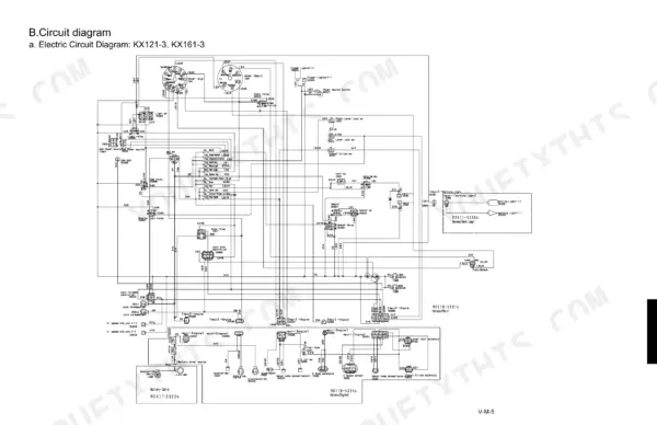
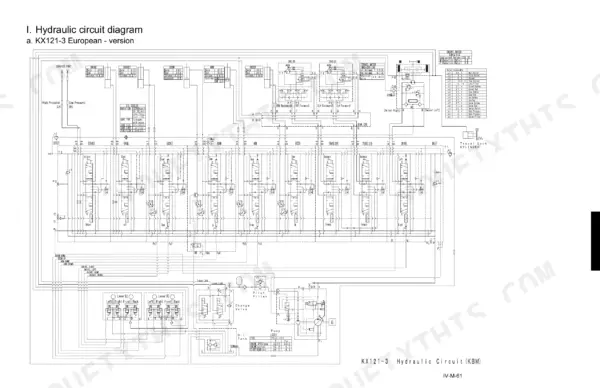
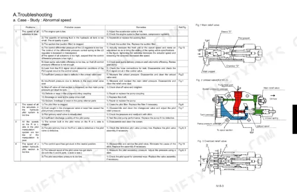
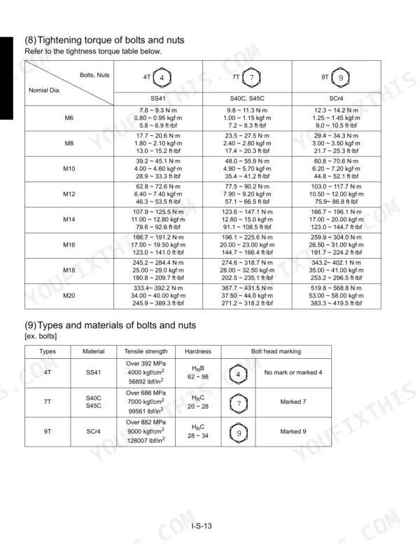
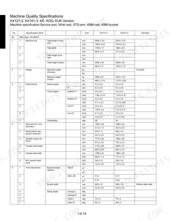
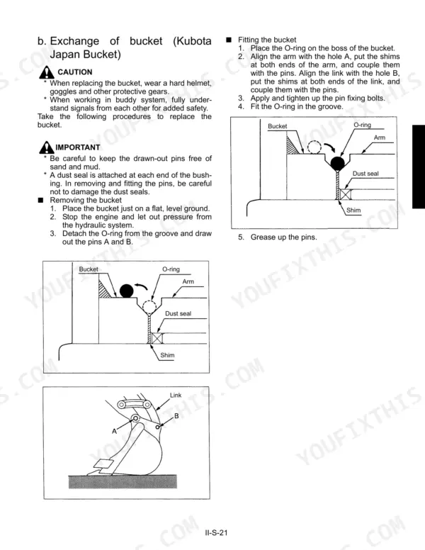
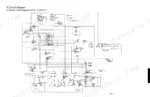
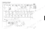
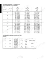
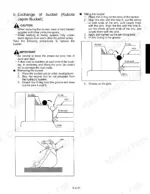
Every page here stays with one machine family: Kubota's compact excavators, the KX121-3, KX161-3, and U45-3 (OEM #97899-60550). Wiring diagrams run across electrical sections, the hydraulic schematics map load-sensing circuits with complete fluid routing, and there are troubleshooting pages covering key fault scenarios plus torque specs covering front attachment pins through undercarriage hardware. Error code references, maintenance interval charts for KTC/KCL/KTA and EU versions, and exploded views of the swing bracket, rubber track, and cab installation fill out the rest. Swivel bearing bolts torque to 259.9-304.0 N-m; 1/4-inch hose fittings tighten to 24.5-29.4 N-m. When a forum thread can't hand you the load-sensing relief valve adjustment sequence, this shop manual can. Download it, pull it up on a tablet at the machine, and get to work.
What's Inside This Manual
| System | Pages | Key Topics |
|---|---|---|
| General | Body and Engine Identification Marks, Safety Precautions for Servicing, Disassembly and Reassembly, Important Safty Process and Critical Functional Process, Important Inspection Items After Reassembling, Servicing Fundamentals, Maintenance Intervals, Water and Oil Quantity, Recommended Oil, Filters, Compatibility Table of Main Components Between U45-3. and KX121-3, 161-3 | |
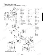
| Machine body(Mechanism Section) | Product Feature, Standard Equipment, Machine Specifications, Component Interchangeability, Machine Structure | |
| Machine body(Service Section) | Specifications, Front Attachment, Upper Structure, Cab Installation : Ktc, Kcl, KTA-version, Under Carriage | |
| Engine | Specifications & Features, Engine Mounting Procedure : KX121-3, 03-M Series Engine WSM | |
| Hydraulic system(Mechanism Section) | Features of Hydraulic System, Hydraulic System Specifications, Main Pump, Control Valve, Pilot Valve, Swivel Motor, Rotary Joint (Swivel Joint), Travel Motor, Hydraulic Circuit Diagram | |
| Hydraulic system(Service Section) | Troubleshooting, Specifications, Relief Valve Pressure Setting, Pump, Load Sensing Control System Data, Cylinder, Swivel Performance, Traveling Performance, Testing, Disassembling and Assembling | |
| Electrical system(Mechanism Section) | Components, Harness Layout & Coupler, Harness Layout & Coupler : KX161-3 AI-version, Circuit Diagram, Function of Main Circuit, Structure and Function of Main Components | |
| Electrical system(Service Section) | Wire Harness Installation, Troubleshooting, Electrical Equipment Specifications | |
| Optional Unit : Air Conditioner(Mechanism Section) | Air Condition System, Function and Structure, Electrical System, Technical Terms | |
| Optional Unit : Air Conditioner(Service Section) | Troubleshooting, Servicing Specifications, Regular Check and Service Points, Precautions at Repairing Refrigerant Cycle, Precaution for Installation and Maintenance, Checking and Charging Refrigerant Cycle, Main Components Servicing | |
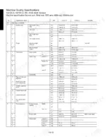
| Optional Unit (Ktc) : Angle Dozer (KX121-3) | Specifications, Machine Quality Specifications, Lubrication Point of Angle Dozer, Dozer Lever, Control Valve, Rotary Joint, Under Carriage, Hydraulic Circuit |
Quick Reference Specifications
| Specification | Value | Page |
|---|---|---|
| Swivel Bearing Tightening torque | 259.9 ~ 304.0 N·m (26.5 ~ 31.0 kgf·m) 191.7 ~ 224.2 ft·lbs | p. 108 |
| Tightening torque for mounting track roller | 259.9 ~ 304.0 N·m (26.5 ~ 31.0 kgf·m) 191.7 ~ 224.2 ft·lbf | p. 144 |
| Main relief valve adjustment procedure | 1. Loosen the lock nut of the relief valve. Using a hex wrench, turn the adjusting screw to reach the specified setting. Then tighten up the lock nut. Clockwise turn raises the pressure, and counterclockwise turn lowers it. 2. Run the engine at the maximum speed. Move the levers and make sure the pressure setting. | p. 398 |
| Hose screw tightening torque (1/8") | 7.8 ~ 11.8 N·m | p. 16 |
| Hose screw tightening torque (1/4") | 24.5 ~ 29.4 N·m | p. 16 |
| Main bearing case screw 1 tightening torque | 46.1 to 50.9 N·m (4.7 to 5.2 kgf·m) 34.0 to 37.6 ft-lbs | p. 247 |
| Idle gear bushing installation procedure | 1. Clean a new idle gear bushing and idle gear bore, and apply engine oil to them. 2. Using an idle gear bushing replacing tool, press in a new bushing (service parts) to the specified dimension. | p. 255 |