
Part of the Kubota Repair Manuals.
This Kubota workshop manual covers the R420α, R520α, R420S, and R520S wheel loaders, including the interim Tier 4 and Stage III A emissions engine variants. It is the combined mechanism and service edition, publication number 97899-62060, running 820 pages with a full text layer.
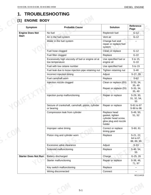
The manual documents every major system on these machines: engine, hydraulics and the LST pump circuit, brakes and power train, the electrical system, and the backhoe attachment. Specification tables, service intervals, tightening torques, and step by step disassembly procedures are all included.
With it you can diagnose a fault, follow the correct teardown sequence, set clearances to spec, and reassemble with confidence, whether you are an owner doing your own maintenance or a mechanic servicing these loaders professionally.
Other edition of this manual
What's Inside This Manual
| System | Pages | Key Topics |
|---|---|---|
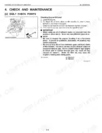
| I. General | 5-28 | Body and Engine Identifications Marks, Safety Precautions for Servicing, Disassembly and Reassembly (a) Safety Measures Before Starting Work, B) Safety Measures During Work |
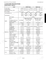
| Ii. Machine BODY-Mechanism | 29-55 | Machine Specifications (a) Specification Table, B) Specification Table, Backhoe-Version, C) Lifting Capacity), Development Concept of Model Change (a) Two Main Concepts |
| Ii. Machine Body & Front Attachment-Service | 56-117 | Machine Specifications (a) Specification Table: PP-version, B) Main Specification: EU-version, C) Dimensional Specifications, D) Specification Table: Backhoe, E) Parts Weight Table |
| Iii. ENGINE-Mechanism | 118-135 | Engine Specifications, Engine Performance Curve, New Emissions Control Engines (a) Outline, B) Engine List for Minor Change |
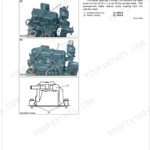
| Iii. ENGINE-Service | 136-354 | Specifications, Engine Assy Dismounting, Engine Accessories (a) Engine Rubber Mount, B) Radiator, Oil Cooler, C) Air Cleaner, D) Muffler, E) Muffler Installation |
| Iv. Hydraulic SYSTEM-Mechanism | 355-391 | Circuit Diagram & Components (a) Hydraulic Circuit Diagram, B) Components Layout), Lst Pump (a) Function of Lst Pump, B) Servo Cylinder, C) High-Pressure Relief Valve |
| Iv. Hydraulic System-Service | 392-573 | Troubleshooting (a) Hydraulic System Does Not Work, B) Weak Lifting, Any Circuit, C) Slow Lifting, D) Cylinder Fall, E) Does Not Travel in Both the F and R Directions |
| V. Brake System and Power Train-Mechanism | 574-589 | Outline, Parking Brake, Service Brake: Axle Brake, Negative Brake Releasing Method, Power Train Components (a) Front Differential Axle Shaft Assy |
| V. Brake System and Power Train-Service | 590-617 | Brake System (a) Negative Brake, B) Parking Valve), Power Train (a) Front Axle, B) Rear Axle, C) Differential Gear, D) Reduction Gear Case Assembly, E) Differential Ass'y Assembly |
| Vi. Electrical System-Mechanism | 618-623 | (A) Electrical Wiring: R420S/Α, R520S/Α, (B) Electrical Circuit Diagram |
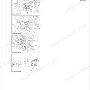
| Vi. Electrical System-Service | 624-689 | Testing, Troubleshooting (a) Battery Discharges Quickly, B) Starter Does Not Drive Engine Properly, C) Forward and Reverse Run Not Selectable, D) Low-Speed Hold Not Effective |
| Vii. BACKHOE-Mechanism | 690-695 | (A) Oil Flow Chart of Backhoe, (B) Hydraulic Circuit Diagram |
| Vii. BACKHOE-Service | 696-743 | Specifications (a) General Dimension, B) Operating Performance, C) Lifting Capacity, D) Hydraulic System Data, E) Bucket, Boom, Arm Data, F) Pin and Bushing Dimensions) |
| Viii. Supplement | 744-815 | Fundamentals of Wheel Loader (a) Glossary, B) Relevant Performance Data), Introduction of Lst System, Introduction of Steering System (a) Steering Performance |
| Conversion Tables | 816-820 |
Quick Reference Specifications
| Specification | Value | Page |
|---|---|---|
| All Models | ||
| Battery liquid level check interval | Every 50 hrs | p. 16 |
| Fuel tank drain interval | Every 50 hrs | p. 16 |
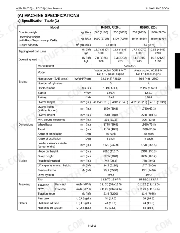
| Hydraulic Oil Tank Capacity | 42 L (11.1 U.S.gals) | p. 59 |
| Fuel Tank Capacity | 54 L (14.3 U.S.gals) | p. 18 |
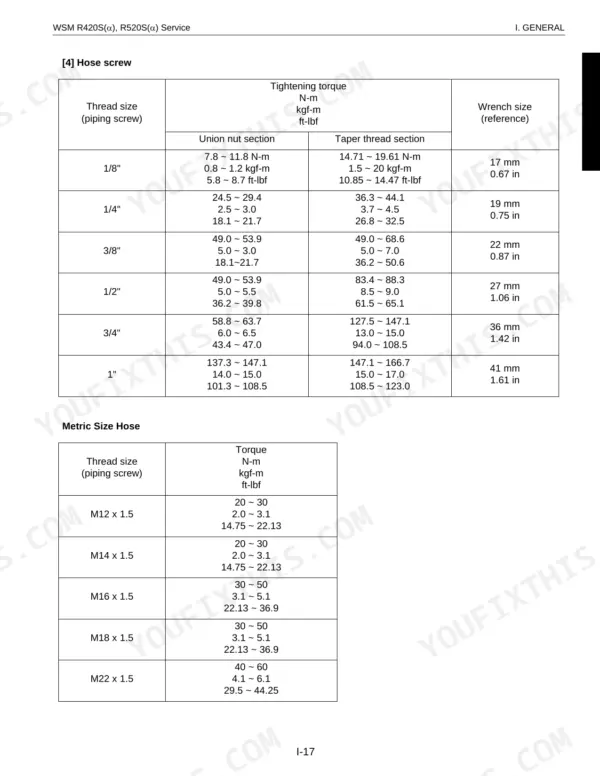
| Hose Screw Tightening Torque (1/8" Union nut section) | 7.8 ~ 11.8 N-m | p. 21 |
| M6 Bolt Tightening Torque (Standard Screw and Bolt) | 7.9 ~ 9.3 N-m | p. 24 |
| Engine Valve Clearance (When Cold) | 0.18 to 0.22 mm | p. 257 |
| R420S, R420α | ||
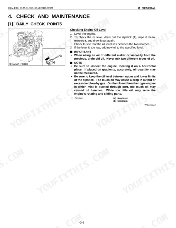
| Engine Oil Capacity (124 mm oil pan depth) (R420S, R420α) | 7.0 L (1.8 U.S.gals) | p. 18 |
| R520S, R520α | ||
| Engine Oil Capacity (124 mm oil pan depth) (R520S, R520α) | 9.5 L (2.5 U.S.gals) | p. 18 |
| R420S | ||
| Tire Pressure (Front/Rear), R420S | 2.6 bar (36.9 ± 1.4 psi) | p. 26 |
| R520S | ||
| Tire Pressure (Front/Rear), R520S | 2.2 bar (31.2 ± 1.4 psi) | p. 26 |
| D1503-M, D1703-M, D1803-M, V2003-M, V2203-M, V2403-M, V2403-M-T, D1703-M-BG, V2003-M-BG, V2003-M-T-BG, V2203-M-BG, V2403-M-BG | ||
| Engine Compression Pressure (When Cranking) | 3.24 to 3.72 MPa | p. 257 |