

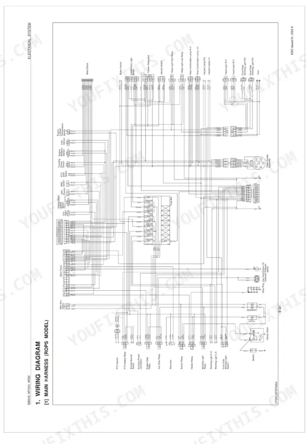
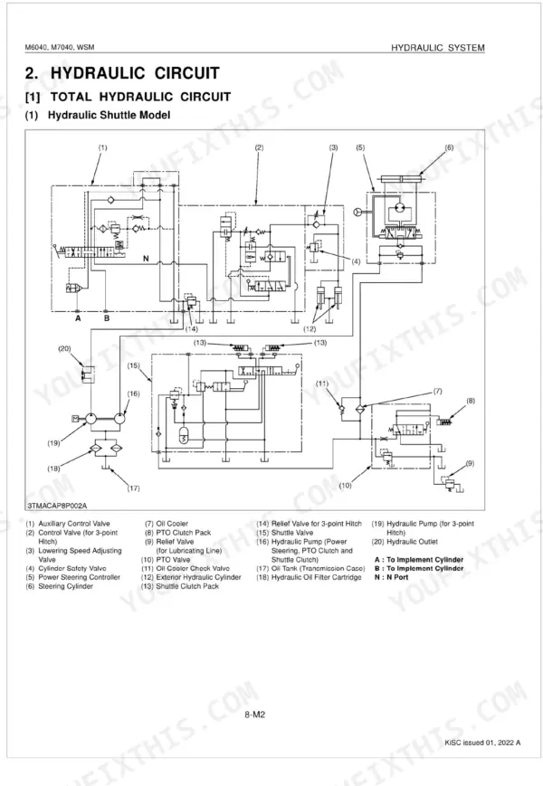
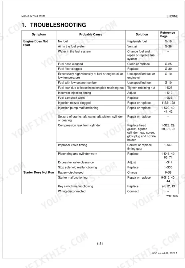
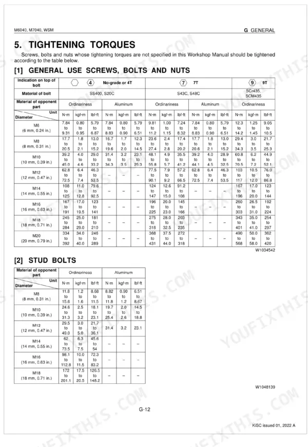
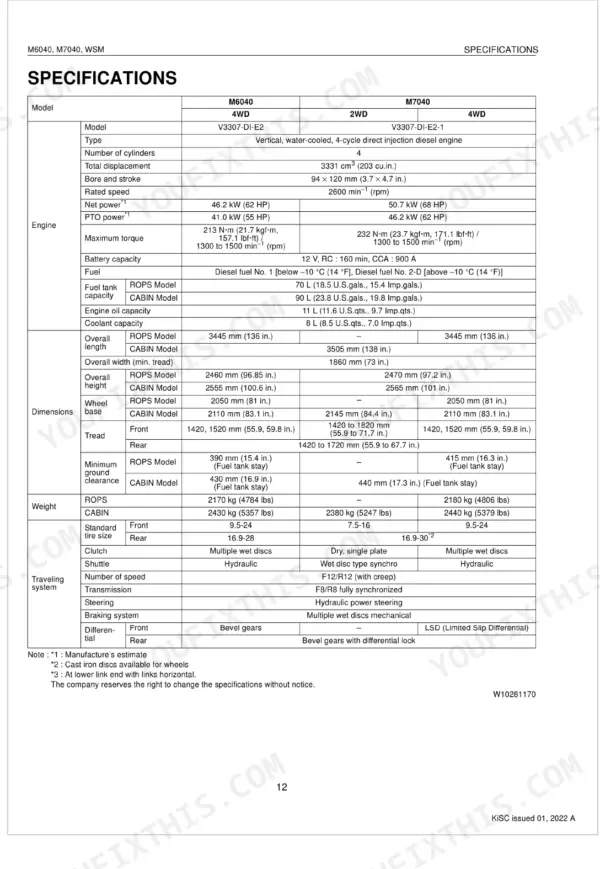
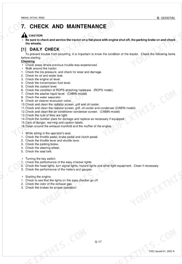


This is the factory Kubota M6040, M7040 Workshop Manual (publication 9Y021-13896), a 564-page service reference for both utility tractors powered by the V3307-DI-E2 diesel engine. It covers every major system on the machine: engine, clutch, transmission, front and rear axle, brakes, steering, the three-point hydraulic system, the electrical system, and the cabin air conditioning system.
Systems are split into a structure and mechanism overview and a dedicated servicing chapter with troubleshooting, servicing specifications, tightening torques, and disassembly and assembly steps. Both the hydraulic shuttle and synchro shuttle transmission models are documented, along with wiring diagrams and fluid capacities such as 11 L engine oil, a 56 L transmission case, and 8.0 L coolant.
Written for owners and independent mechanics, this PDF provides the manufacturer procedures needed to service the M6040 and M7040 properly. Instant download after purchase.
What's Inside This Manual
| System | Pages | Key Topics |
|---|---|---|
| General | 20-106 | Tractor Identification (Model Name and Serial Numbers), Cylinder Number, Handling Precautions for Electrical Parts and Wiring (Battery, Fuse, Connector, Handling of Circuit Tester) |
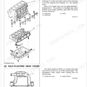
| Engine | 107-124 | Engine Body, Cylinder Block, Cooling Jacket, Half-Floating Head Cover, Cylinder Head, Center Direct Injection System (E-Cdis), Gear Train Configuration, Piston |
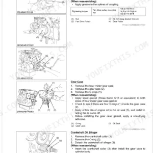
| Servicing Engine | 125-197 | Troubleshooting, Servicing Specifications, Tightening Torques, Checking, Disassembling and Servicing (Checking and Adjusting, Preparation, Disassembling and Assembling) |
| Clutch | 198-204 | Traveling Clutch (Structure, Oil Flow), PTO Clutch (Structure, Oil Flow, Valve) |
| Servicing Clutch | 205-235 | Traveling Clutch, PTO Clutch, Preparation, Damper Disc (Hydraulic Shuttle Model), Clutch Disc (Synchro Shuttle Model), PTO Clutch Valve, PTO Clutch Pack, Traveling Clutch (Hydraulic Shuttle Model) |
| Transmission | 236-253 | Structure (Hydraulic Shuttle Model, Synchro Shuttle Model), Power Train for Traveling Gear (Hydraulic Shuttle, Synchro Shuttle, Hydraulic Shuttle Valve, Hi-Lo/Creep Shift Section) |
| Servicing Transmission | 254-309 | Troubleshooting, Servicing Specifications, Tightening Torques, Checking and Adjusting (Shuttle Lever, Main Gear Shifting, Shuttle Valve) |
| Rear Axle | 310-312 | Structure, Power Transmission, Speed Reduction, Rear Axles Function |
| Servicing Rear Axle | 313-321 | ROPS, Lift Rod, Lower Link, Rear Wheel, Fender, Fuel Tank, Hydraulic Cylinder, Rear Axle Case |
| Brakes | 322-324 | Structure, Brake Pedal Type, Wet Disc Brakes, Parking Brake |
| Servicing Brakes | 325-332 | Brake Pedal, Cam Plate, Cam Plate and Ball, Brake Disc, Plate, Brake Plate, ROPS Under Frame, Rear Wheel |
| Front Axle | 333-337 | Structure (Wheel Drive, Limited Slip Differential [M7040]) |
| Servicing Front Axle | 338-365 | Troubleshooting, Servicing Specifications, Tightening Torques, Checking, Disassembling and Servicing (Checking and Adjusting, Preparation, Disassembling and Assembling) |
| Steering | 366-369 | Steering Mechanism, Full Hydrostatic Power Steering, Steering Cylinder |
| Servicing Steering | 370-387 | Troubleshooting, Servicing Specifications, Tightening Torques, Checking, Disassembling and Servicing (Checking and Adjusting, Preparation, Disassembling and Assembling) |
| Hydraulic System | 388-398 | Structure, Hydraulic Circuit (Total Hydraulic Circuit), Three Point Hitch Hydraulic System (Hydraulic Block, Linkage Mechanism, Hydraulic Cylinder) |
| Servicing Hydraulic System | 399-426 | Troubleshooting, Servicing Specifications, Tightening Torques, Checking and Adjusting (Hydraulic Pump, Relief and Safety Valve, Position and Draft Control Linkage) |
| Electrical System | 427-452 | Wiring Diagram (Main Harness, Cabin Harness, Engine Harness), Electrical Circuit Retailed Chart (Wiring Color), Starting System (System Outline and Electrical Circuit) |
| Servicing Electrical System | 453-500 | Battery, Fuse, Grounding and Connector, Main Switch, Glow Plug, Starter Motor, Engine Stop Solenoid, Alternator |
| Cabin | 501-510 | Air Conditioning System (Structure, Compressor, Air Conditioner Unit, System Control, Air Flow, Air Control Vent, Electrical System) |
| Servicing Cabin | 511-564 | Precautions at Repairing Refrigerant Cycle, Handling of Service Tools, Checking and Charging Refrigerant Cycle, Checking with Manifold Gauge, Discharging, Evacuating and Charging |
Quick Reference Specifications
| Specification | Value | Page |
|---|---|---|
| Engine crankcase (with filter) | 11 L (11.6 U.S.qts., 9.7 Imp.qts.) | p. 31 |
| Transmission case | 56 L (59.2 U.S.qts., 49.3 Imp.qts.) | p. 31 |
| Coolant | 8.0 L (8.5 U.S.qts., 7.0 Imp.qts.) | p. 31 |
| Fuel filter replacement interval | every 400 Hr | p. 36 |
| Cylinder head mounting screw (bolt head with stamp "10") | 186 to 196 N-m (19.0 to 20.0 kgf-m, 137 to 145 lbf-ft) | p. 136 |
| Cylinder head mounting screw (bolt head with no stamp) | 165 to 175 N-m (16.9 to 17.8 kgf-m, 122 to 129 lbf-ft) | p. 136 |
| Clutch Pedal Free Travel (Hydraulic Shuttle Model) | 15 to 25 mm | p. 209 |
| PTO Clutch Relief Valve Setting Pressure | 2.16 to 2.26 MPa | p. 210 |
| Transmission Case and Clutch Housing Mounting Screw and Nut (M14, 9T) Torque | 166.7 to 196.1 N-m | p. 258 |
