

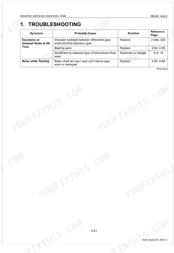
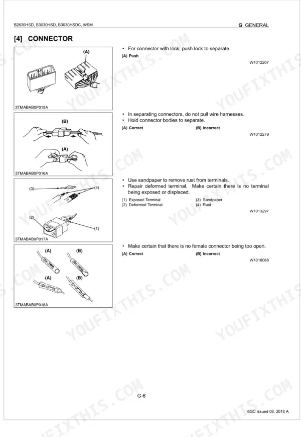
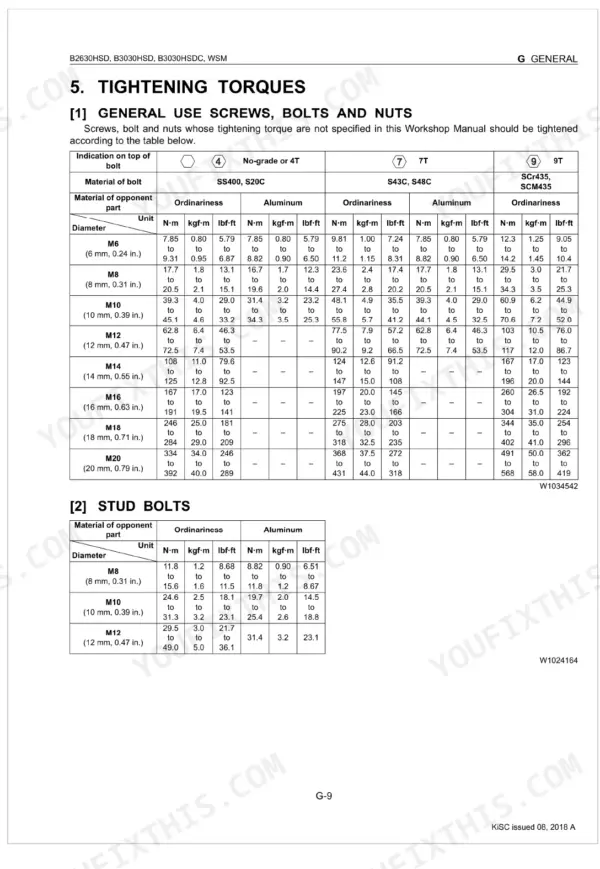
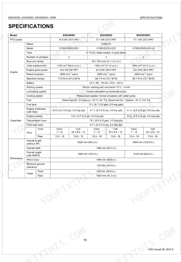



This is the Kubota Workshop Manual for the B2630HSD, B3030HSD, and B3030HSDC compact tractors, publication 9Y011-13494. Across 498 pages it documents these three models and their Kubota diesel engines, the D1105 and V1505 series.
You get mechanism descriptions, troubleshooting, servicing specifications, and tightening torques for the engine, transmission, front and rear axles, brakes, power steering, the hydraulic system, the electrical system with wiring diagrams, and the cab with its air conditioning. Fluid capacities, valve clearances, and torque values are given with page references.
This is the reference an owner or independent mechanic needs to chase hard steering, a shutdown with clicking, or weak hydraulics after winter storage, and to carry out the repair with factory procedures rather than booking dealer time.
Complete the set for your B2630HSD, B3030HSD, B3030HSDC
- Parts Catalog: Kubota B3030HSD Parts Catalog
What's Inside This Manual
| System | Pages | Key Topics |
|---|---|---|
| Safety Instructions | Safety First, Before Servicing and Repairing, Safety Starting, Safety Working, Avoid Fires, Ventilate Work Area, Prevent Acid Burns, Dispose of Fluids Properly | |
| Brakes | Safety Decals, ROPS and Cabin, Cabin, Care of Danger, Warning and Caution Labels | |
| Specifications | PTO Power, Engine, Capacities, Dimensions, Tread, Travelling System, Hydraulic System, PTO System | |
| General | Tractor Identification, General Precaution, Wiring | |
| Engine | Battery, Fuse, Connector, Handling of Circuit Tester, Lubricants, Fuel and Coolant, General Use Screws, Bolts and Nuts, Stud Bolts, Maintenance Check List | |
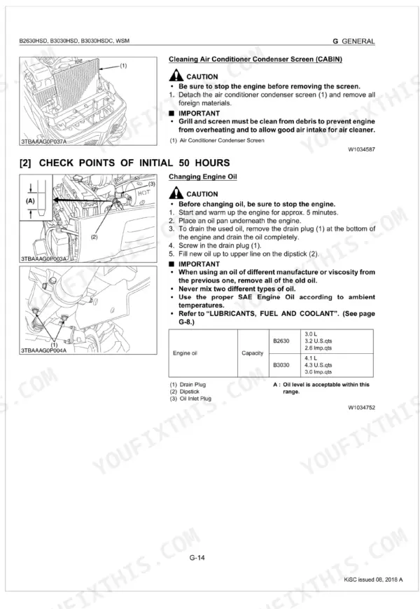
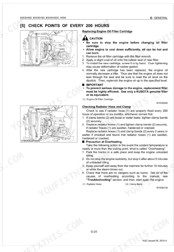
| Transmission | Check and Maintenance, Daily Check, Check Points of Initial 50 Hours, Tractor Section, Engine Section, Check Points of Every 50 Hours, Check Points of Every 100 Hours, Check Points of Every 200 Hours | |
| Rear Axle | Tire Liquid Injection and Ballast, Preparation | |
| Front Axle | Control Levers, Brake Pedals, Main Frame, Hydraulic Pipes, Clutch Housing, Steel Plate, Clutch Shaft, Ball Bearing | |
| Steering | Trunnion Shaft, Charge Relief Valve, PTO Clutch Case, Bevel Pinion Shaft, Range Gear Shaft, Front Wheel Drive Shaft, 4WD Shift Lever, Independent PTO Clutch Shifter | |
| Hydraulic System | Brake Pedal, Brake Disks, Brake Plates, Brake Shaft, Brake Cam Plate, Brake Cam Lever, Front Axle, Differential Lock Clutch | |
| Electrical System | Power Steering Cylinder, Hydraulic Pump, Hydraulic Block, Power Steering, Independent PTO, Three Points Hydraulic System | |
| Cabin | Precautions at Repairing Refrigerant Cycle, Handling of Service Tools, Checking and Charging Refrigerant Cycle |
Quick Reference Specifications
| Specification | Value | Page |
|---|---|---|
| Front wheel mounting nut torque | 77 to 90 N·m (7.9 to 9.2 kgf·m, 57 to 67 lbf·ft) | p. 37 |
| Rear wheel mounting bolts torque | 196 to 225 N·m (20 to 23 kgf·m, 145 to 166 lbf·ft) | p. 37 |
| Cylinder head screw torque | 63.7 to 68.6 N·m (6.5 to 7.0 kgf·m, 47.0 to 50.6 lbf·ft) | p. 98 |
| Steering center seal | Not found as a serviceable part with explicit specifications. The manual suggests replacing the entire steering controller if oil leaks. | p. 261 |
| Power steering hose for power steering controller torque | 24 to 28 N·m (2.5 to 2.8 kgf·m, 18 to 20 lbf·ft) | p. 158 |
| Power steering hose for power steering cylinder torque | 24.0 to 28.0 N·m (2.5 to 2.9 kgf·m, 17.7 to 20.7 lbf·ft) | p. 258 |
| Fan Belt tension (deflection) | 7.0 to 9.0 mm (0.28 to 0.35 in.) | p. 42 |
| Air Conditioner Drive Belt tension (deflection) | 10 to 12 mm (0.39 to 0.47 in.) deflection at 98 N (10 kgf, 22 lbf) of force | p. 404 |
| Fuel tank capacity | 31 L (8.1 U.S.gals, 6.8 Imp.gals) | p. 27 |
| Transmission case capacity | 15 L (4.0 U.S.gals, 3.3 Imp.gals) | p. 27 |
| Brake pedal shaft greasing points | 1 greasing point | p. 27 |
| Top link greasing points | 1 greasing point | p. 27 |
