
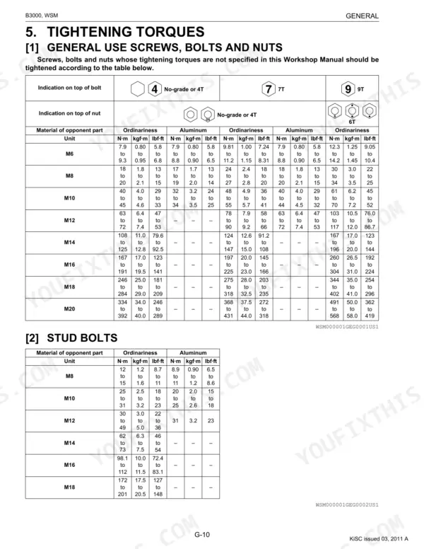
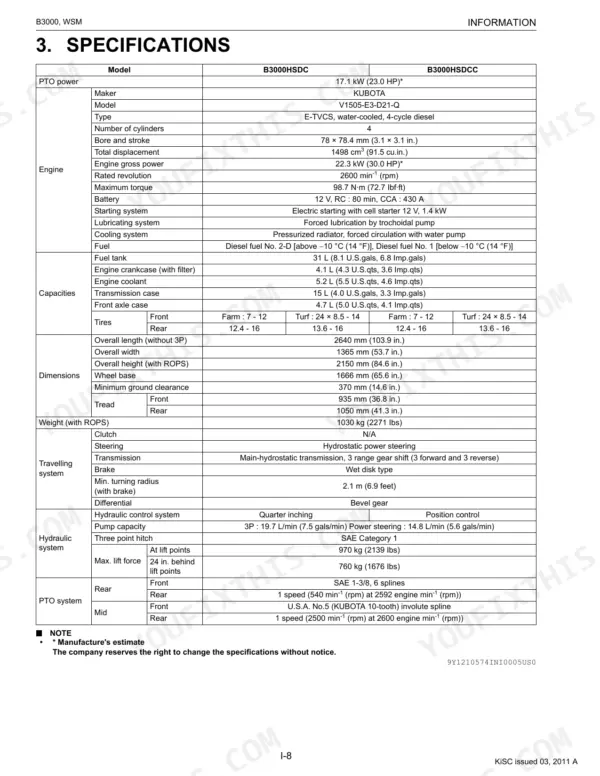
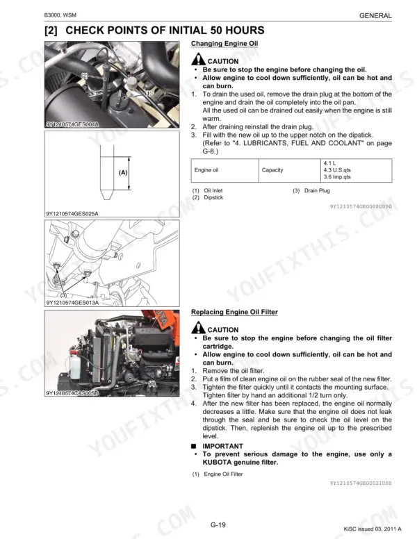
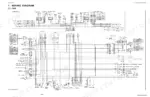
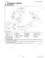
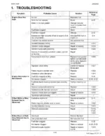
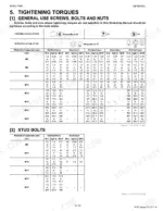
Kubota built two versions of the B3000, the HSDC and HSDCC, and this OEM workshop manual (#9Y111-05740) treats both across 433 pages, from engine teardown to cab air conditioning rebuild. The hydraulic circuit diagrams cover both configurations. Cab wiring maps the OPC safety system, lighting, and Easy Checker, while exploded transmission views lay out the hydrostatic pump and motor, cruise control linkage, and PTO sections. Torque tables run from general metric fasteners to hydraulic fittings and stud bolts, with a troubleshooting section behind them. Set the power steering hose fitting at 24-28 N·m, the independent PTO control valve bolt at 40-44 N·m, and check clutch disc thickness at 1.70-1.90 mm before reassembly. One source per spec, instead of three. Bookmarked and keyword-searchable, so any system pulls up on your tablet at the bench.
What's Inside This Kubota B3000 Manual
| System | Pages | Key Topics |
|---|---|---|
| To the Reader | Information | |
| G General | Tractor Identification, General Precautions, Wiring, Battery, Fuse, Connector, Handling of Circuit Tester, Color of Wiring | |
| Engine | Tractor Section, Engine Section, Preparation | |
| Transmission | Front Case, Hydrostatic Transmission, Pump and Motor, Oil Flow and Valves, Control Linkage, Cruise Control, Cruise Control Linkage, Range Gear Shift Section | |
| Rear Axle | Excessive or Unusual Noise at All Time, Noise While Turning, Rear Axle Case Mounting Bolt (M10), Draining Transmission Fluid, Separating Transmission Assembly, Rear Axle (LH) and Rear Axle (RH) Assembly, Differential Lock Shift Fork, Rear Axle Shaft | |
| Brakes | Operation, Features of Wet Disc Brakes, During Braking, Uneven Braking Force, Brake Drags, Poor Braking Force, Brake Pedal, Cam Plate and Bearing Holder | |
| Front Axle | Front Wheels Wander to Right or Left, Front Wheels CAN Not Be Driven, Noise, Front Wheel Alignment, Differential Pinion to Differential Case, Yoke Shaft to Differential Case, Spiral Bevel Pinion Shaft | |
| Steering | Hydraulic Circuit, Steering Controller, Steering Cylinder | |
| Hydraulic System | Hydraulic Circuit, B3000HSDC, B3000HSDCC, Hydraulic Pump, Hydraulic Block, Power Steering, Power Steering Controller, Steering Cylinder | |
| Electrical System | Wiring Diagram, Cab, Engine Starting System and Stopping System, Opc System Circuit, Safety Switch, Controller, Safety Switch Position and Engine Condition, Lighting System | |
| Cabin | Outline of Air Conditioning System, Air Flow, Air Control Vent, Control Panel, Operation, Refrigeration System, Compressor, Condenser |
Quick Reference Specifications
| Specification | Value | Page |
|---|---|---|
| Power steering hose for power steering controller | 24 to 28 N·m | p. 90 |
| Clutch Disc Thickness | 1.70 to 1.90 mm | p. 163 |
| Independent PTO control valve mounting bolt (M10) | 40 to 44 N·m | p. 165 |
| Battery type: 55B24L (S)-MF, Volts (V) | 12 | p. 41 |
| Capacity at 5H.R | 36 | p. 41 |
| Commutator O.D. Factory specification | 28.0 mm | p. 326 |
| Mica Undercut Factory specification | 0.60 mm | p. 326 |
| Relief valve setting pressure Factory specification | 15.0 to 16.0 MPa | p. 288 |
| Engine Oil Capacity (with filter) | 4.1 L | p. 24 |
| Transmission Case Capacity | 15 L | p. 24 |
| Front Axle Case Capacity | 4.7 L | p. 24 |
| Engine Compression Pressure (Factory Specification) | 3.73 to 4.11 MPa | p. 85 |
Kubota B3000 Common Problems This Manual Covers
Kubota B3000 PTO won't engage, slips under load, or drops out mid-task
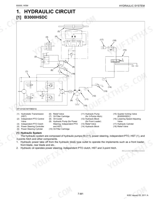
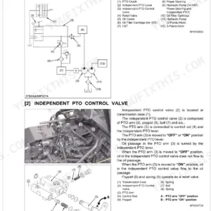
Check the engagement linkage for binding or misadjustment before removing the cover. Torque the independent PTO control valve mounting bolts to 40 to 44 N·m (page 165). Inspect the clutch disc; if it's worn thin, it won't hold under load. Pull the hydraulic circuit diagram on page 262 to trace the full PTO control circuit.
Manual Section: Hydraulic System Troubleshooting (Independent PTO) p. 165Hydraulic lift arms move slowly, can't hold implement weight, or stop mid-cycle
Check fluid level and condition before testing anything else; milky or foamy fluid means water or air contamination. Verify the hydraulic relief valve is set to 15.0 to 16.0 MPa (page 288); pressure below that range is why lifts feel weak. Inspect the filter for restriction, then trace the schematic on page 262 to isolate pump or valve issues.
Manual Section: Hydraulic System Troubleshooting (3-Points Hitch) p. 288Engine cranks but won't fire, starts hard in cold weather, or dies unexpectedly
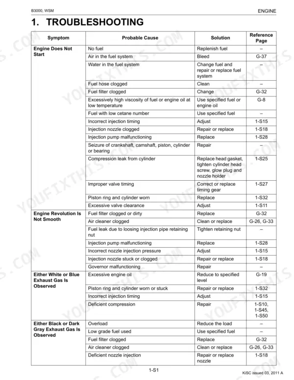
Verify the battery meets the 55B24L (S)-MF spec: 12V, 430 cold cranking amps (page 41). If the engine cranks slowly in cold weather, that number matters. Work through the engine troubleshooting procedures to check fuel delivery and safety interlock status. If the starter is suspect, measure brush length against the 14.0 mm factory spec (page 326).
Manual Section: Engine TroubleshootingHydrostatic transmission vibrates, loses drive in one direction, or overheats under load
Fill the transmission to its 15 L capacity (page 24) before diagnosing anything mechanical; low fluid alone causes noise and power loss in hydrostatic systems. Check that the HST charge relief valve holds 0.4 to 0.6 MPa (page 163). If pressure is correct and vibration persists in one direction only, the pump or motor internals are the next step.
Manual Section: Transmission Troubleshooting (Hydrostatic Transmission) p. 163Coolant temperature gauge climbs into red during heavy mowing or loader work
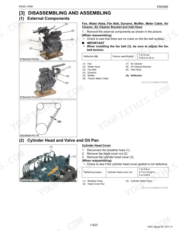
Check fan belt deflection first: correct tension is 7.0 to 9.0 mm at mid-span (page 93). Clear debris from the radiator screen and verify coolant level before the engine gets back under load. If belt and coolant check out, work the overheating procedures, which cover thermostat function and water pump flow.
Manual Section: Engine TroubleshootingFrequently Asked Questions
How do I resume operation of a Kubota B3000 after a safety shutdown?
The Kubota B3000's Operator Presence Control (OPC) system automatically stops the engine if safety conditions are not met. To resume operation after a safety shutdown, ensure the Independent PTO Lever Switch is in the "ON" (Disengaged) position and the HST Pedal Switch is in the "ON" (Neutral) position. These conditions are required for the engine to start. p. 315
What are the torque specifications for wheel lug nuts, hydraulic cylinder mounting bolts, and engine components on a Kubota B3000?
For the Kubota B3000, front wheel mounting nuts should be tightened to 77 to 90 N·m (57 to 67 lbf·ft). Rear wheel mounting bolts require 196 to 225 N·m (145 to 166 lbf·ft), and rear wheel mounting nuts require 167 to 191 N·m (123 to 141 lbf·ft). Engine cylinder head screws are tightened to 64 to 68 N·m (47 to 50 lbf·ft), and hydraulic cylinder mounting bolts (M10) are 40 to 44 N·m (29 to 32 lbf·ft). p. 72
The Kubota B3000 tractor shut off unexpectedly. How do I troubleshoot the seat safety switch?
The Operator Presence Control (OPC) system on the B3000 tractor automatically stops the engine if the operator stands up from the seat while the PTO lever, independent PTO shift lever, or HST pedal is engaged. To troubleshoot the seat safety switch, disconnect its leads and measure resistance across the terminals. If continuity is not 0 Ω when the seat switch is pushed, or not infinity when not pushed, the switch is faulty and needs replacement. Refer to page 8-S14 for detailed continuity checks. p. 307
What are the output specifications for the Kubota B3000 hydraulic pump?
The hydraulic pump for the 3-points hitch on the Kubota B3000 has a displacement of 19.7 L/min (5.20 U.S.gals/min, 4.33 Imp.gals/min) at 2600 min-1 (rpm) at no load. For power steering, the hydraulic pump displacement is 14.8 L/min (3.91 U.S.gals/min, 3.26 Imp.gals/min) at 2600 min-1 (rpm) at no load. p. 264
Is this Service Manual a digital download?
A 433-page Service Manual in searchable PDF format, available the moment you complete checkout. View on computer, tablet, or phone, no shipping wait.
Can I print pages of this manual for my own shop?
Yes. Print a chapter or just the pages for the job at hand, for use in your own shop. Any home or office printer works.
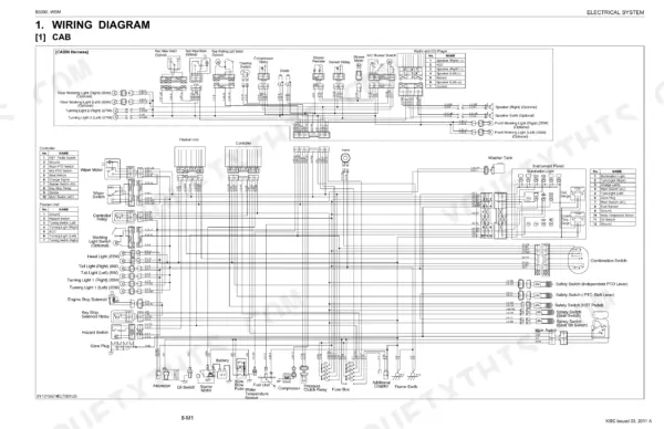
Are there wiring harness diagrams in this Kubota B3000 manual?
Included. The Kubota B3000 Service Manual covers complete wiring harness diagrams, electrical circuits, and connector pinouts.

Reviews
There are no reviews yet.