


Part of the Kubota Repair Manuals.
The Kubota ZG327A Workshop Manual is the factory service book for the ZG327A zero-turn mower, covering 288 pages of mechanism and servicing information.
It covers the KGZ770-MA1 engine, the HST-driven transaxle, the front axle, the hydraulic deck-lift system, the electrical system, and the mower deck with its 1524 mm cutting width. Each area gives structure and function first, then troubleshooting, servicing specifications, and tightening torques, so you can diagnose a fault, set the right clearances and pressures, and reassemble to spec.
The manual downloads as a searchable, bookmarked PDF. Jump straight to the Engine, Transaxle, Hydraulic, Electrical, or Mower section on a phone, tablet, or shop computer, and print only the pages you need for the repair in front of you.
What's Inside This Manual
| System | Pages | Key Topics |
|---|---|---|
| Record of Revisions | 3 | |
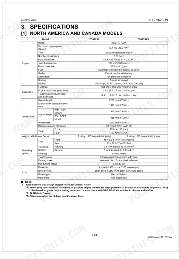
| Information | 4-22 | Safety First, Safety Decals, Specifications (North America and Canada Models), Dimensions |
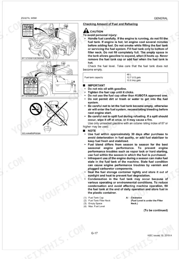
| General | 23-81 | Identification, Cylinder Number, Handling Precautions for Electrical Parts and Wiring (Battery, Fuse, Connector, Handling of Circuit Tester, Color of Wiring), Lubricants and Fuel |
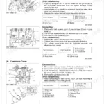
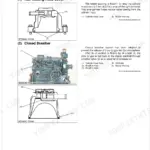
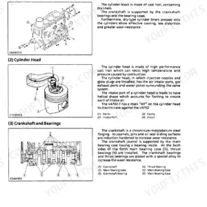
| Engine Mechanism | 82-104 | Feature, Engine Body (Cylinder Head, Closed Breather, Camshaft, Combustion Chamber, Piston and Piston Ring, Gear Train Made of Reinforced Nylon) |
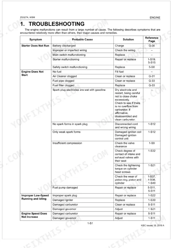
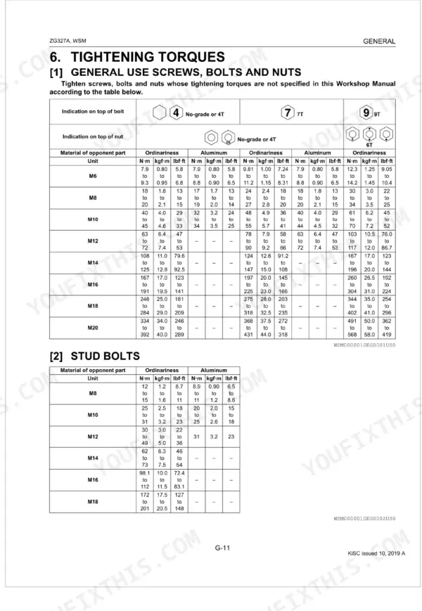
| Engine Servicing | 105-147 | Troubleshooting, Servicing Specifications, Tightening Torques (General Use Screws, Bolts and Nuts, Special Use Screws, Bolts and Nuts), Checking |
| Transaxle Mechanism | 148-159 | Travelling System, Hydrostatic Transmission, Check Valve and High Pressure Relief Valve, Power Trains Operation, Control Linkage, Final Reduction Gear Section, PTO System, Parking Brake |
| Transaxle Servicing | 160-202 | HST, Parking Brake, Separating Transaxle Assembly, Disassembling Transaxle Center Case, Disassembling PTO Clutch Shaft Assembly, Disassembling Rear Axle Gear Case, Hydrostatic Transmission, Transmission Case |
| Front Axle Mechanism | 203-204 | Structure, Front Tire Assembly, Wheel Bracket Mounting |
| Front Axle Servicing | 205-210 | Front Wheels, Wheel Bracket, Wheel Bolt, Lock Nut, Wheel Cup, Plate Spring, Bearing, Oil Seal |
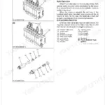
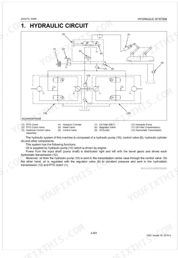
| Hydraulic System Mechanism | 211-217 | Hydraulic Circuit, Hydraulic Pump, Hydraulic Control Valve (Operation), Lift Cylinder, Mower Linkage |
| Hydraulic System Servicing | 218-232 | Troubleshooting, Servicing Specifications, Tightening Torques, Checking, Disassembling and Servicing (Hydraulic Control Valve, Pump and Cylinder, Lifting Linkage) |
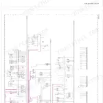
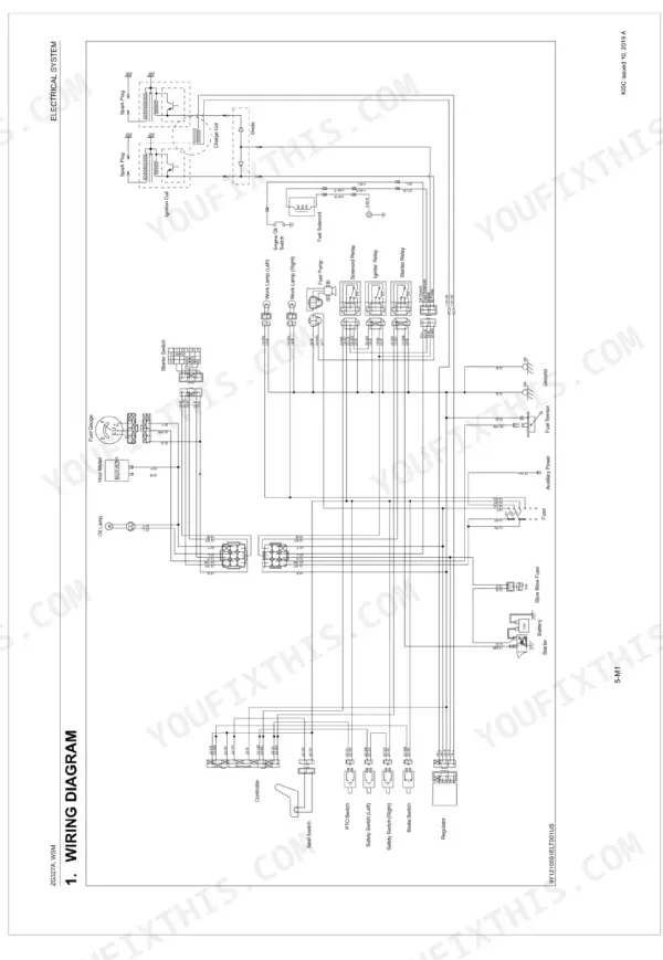
| Electrical System Mechanism | 233-243 | Wiring Diagram, Starting System (Starter, Safety Switch, Relay, Fuel Pump, Fuel Cut Off Solenoid), Charging System (Generator, Regulator), Gauges (Fuel Quantity, Easy Checker™) |
| Electrical System Servicing | 244-262 | Battery, Main Switch, Safety Switches, Starter, Fuel Pump, Fuel Cut Off Solenoid, Charging System, Lighting System |
| Mower Mechanism | 263-265 | Structure (Power Transmission, Lifting Mechanism, Mower Lifting Operation, Mower Lifting Safety) |
| Mower Servicing | 266-288 | Anti-Scalp Rollers, Left and Right Cutting Height, Front and Rear Cutting Height, Universal Joint and Belt Covers, Mower Blades, Blade Boss, Gear Box, Center Pulley Holder |
Quick Reference Specifications
| Specification | Value | Page |
|---|---|---|
| Fuel tank capacity | 48 L (12.7 U.S.gals, 10.6 Imp.gals) | p. 33 |
| Engine crankcase (with filter) capacity | 2.0 L (2.1 U.S.qts, 1.8 Imp.qts) | p. 33 |
| Engine Oil Capacity (with filter) | 2.0 L | p. 18 |
| Transmission Fluid Capacity (including rear axle gear case) | 12.1 L | p. 18 |
| Engine Oil Change Interval | Every 100 Hr | p. 37 |
| Engine Oil Filter Replacement Interval | Every 200 Hr | p. 37 |
| Spark Plug Air Gap (Factory specification) | 0.60 to 0.70 mm | p. 111 |
| Cylinder Head Screw Torque (M10 x 1.5) | 41.2 to 50.0 N·m | p. 112 |
| Mower Blade Screw Torque | 103 to 118 N·m | p. 269 |
| HST Relief Valve Setting Pressure | 20.0 to 22.0 MPa | p. 163 |
| Relief Valve (Control Valve) Setting Pressure | 5.5 to 7.0 MPa | p. 220 |
| Battery Voltage | More than 12 V | p. 247 |