


Part of the Kubota Repair Manuals.
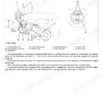
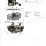
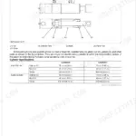
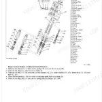
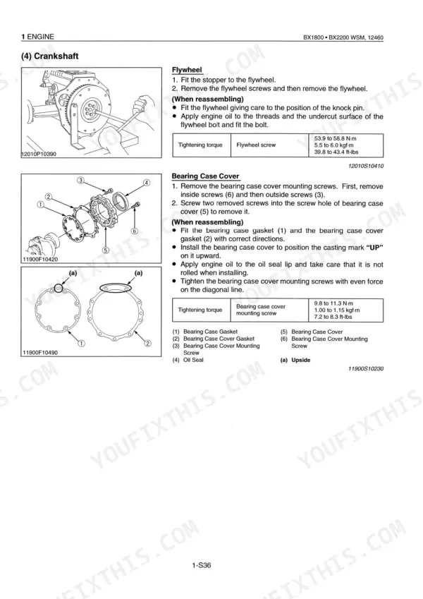
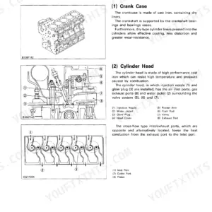
This is the Kubota BX1800 and BX2200 Workshop Manual, a 293 page PDF covering both sub-compact tractors and their D722-E-BX and D905-E-BX diesel engines. It opens with specifications, travelling speed, and dimensions, then works through the general section, engine, transaxle, front axle, steering, hydraulic system, and electrical system.
Each system is broken into mechanism and servicing, so you can learn how a part works before troubleshooting, disassembling, and reassembling it. That makes it usable for no-start diagnosis, cooling and hydraulic problems, transaxle work, and full electrical tracing with the wiring diagram.
Reference values include PTO power of 10.2 kW on the BX1800 and 12.4 kW on the BX2200, front wheel mounting screw torque of 122 to 146 N-m, and a hydraulic relief valve setting of 12.3 to 12.7 MPa. Instant PDF download that prints cleanly for bench use.
What's Inside This Manual
| System | Pages | Key Topics |
|---|---|---|
| Safety First | 3-5 | |
| Safety Decals | 6-7 | |
| Specifications | 8 | Model, PTO Power, Engine, Capacities, Dimensions, Weight |
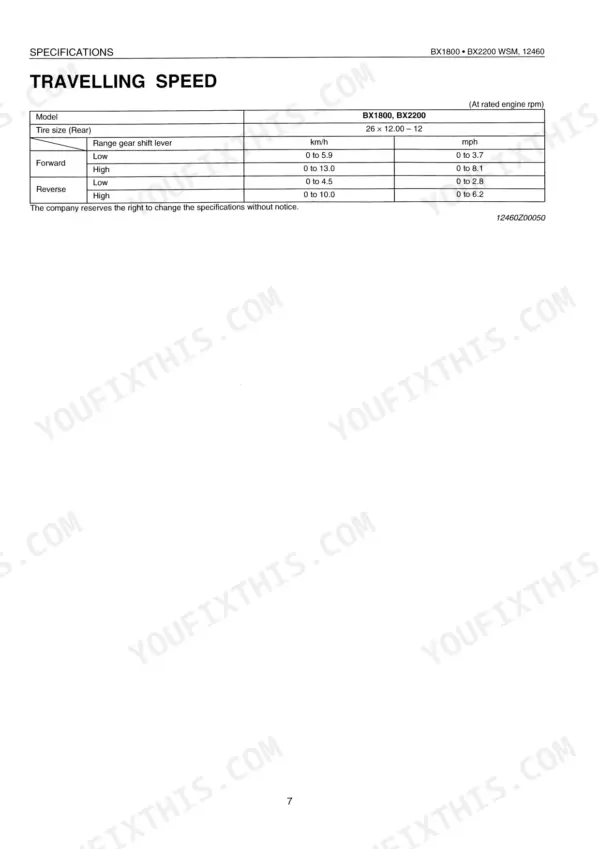
| Travelling Speed | 9 | Model, Tire Size (Rear), Range Gear Shift Lever |
| Dimensions | 10-11 | |
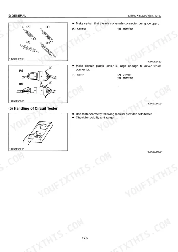
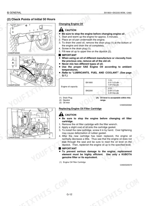
| G General | 12-54 | Tractor Identification, General Precautions, Electrical Parts and Wiring, Lubricants, Fuel and Coolant, Tightening Torques |
| Engine | 55-146 | Engine Body, Lubricating System, Cooling System, Fuel System |
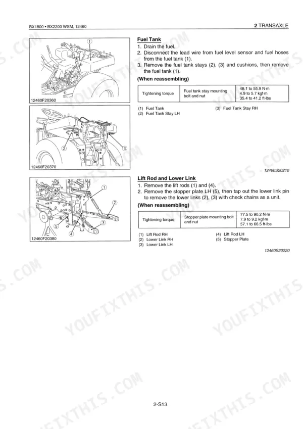
| Transaxle | 147-200 | Structure, Travelling System, PTO System, Others |
| Front Axle | 201-219 | Structure, Front Wheel Alignment, Axle, Bevel Gear, Differential Gear Assembly, Toe-In |
| Steering | 220-231 | Hydraulic Circuit, Steering Controller, Steering Cylinder |
| Hydraulic System | 232-256 | Hydraulic Circuit, Hydraulic Pump, Hydraulic Control Valve, Flow Priority Valve, Relief Valve, Hydraulic Cylinder |
| Electrical System | 257-292 | Wiring Diagram, Starting System, Charging System, Lighting System, Gauges |
Quick Reference Specifications
| Specification | Value | Page |
|---|---|---|
| Cylinder head screw torque | 37.2 to 42.1 N·m (3.8 to 4.3 kgf·m, 28.0 to 31.0 ft-lbs) | p. 97 |
| Front wheel mounting screws torque | 122 to 146 N·m (12.5 to 15.0 kgf·m, 90 to 108 ft-lbs) | p. 20 |
| Rear wheel mounting screws torque | 88 to 104 N·m (9.0 to 10.6 kgf·m, 65 to 79 ft-lbs) | p. 20 |
| Battery terminal nut torque | 2 N·m (0.2 kgf·m, 1.5 ft-lbs) | p. 24 |
| Battery terminal connection potential difference | Less than 0.1 V | p. 277 |
| Safety switch distance A | 3 to 5 mm (0.118 to 0.197 in.) | p. 281 |
| ROPS mounting nut torque | 124 to 147 N·m (12.6 to 15.0 kgf·m, 91 to 108 ft-lbs) | p. 177 |
| Front tire inflation pressure (18 x 8.50 - 8 Turf) | 150 kPa (1.5 kgf/cm², 22 psi) | p. 49 |
| Rear tire inflation pressure (26 x 12.00 - 12 Turf) | 140 kPa (1.4 kgf/cm², 20 psi) | p. 49 |
| Thermostat valve opening temperature (at beginning) | 80.5 to 83.5 °C (176.9 to 182.3 °F) | p. 84 |
| Thermostat valve opening temperature (opened completely) | 95 °C (203 °F) | p. 84 |
| PTO Power | 10.2 kW | p. 8 |