

Part of the Kubota Repair Manuals.
This Kubota Workshop Manual covers the LA271, LA301, LA351, LA401, LA272, LA302, LA352, and LA402 front loaders in 62 pages. Unlike an operator handbook, this is the factory service manual, split into a Mechanism half that explains how the loaders work and a Servicing half for troubleshooting and repair.
The Mechanism section details the hydraulic circuit, the control valve assemblies for each model group, the relief valve, and the boom and bucket cylinders. The Servicing section covers general maintenance, a full troubleshooting guide, servicing specifications, allowable wear limits, and complete tightening torque tables.
This is the manual to reach for when a loader drifts down, will not hold position, or loses lift power, and you need seal, valve, and torque figures to fix it properly. It downloads as a PDF and prints on demand, so you can keep the relevant pages at the bench.
Complete the set for your LA271–LA402 Series
- Parts Catalog: Kubota LA272 Tractor Loader Parts Catalog
- Parts Catalog: Kubota LA301, LA351 Loader Parts Catalog
- Parts Catalog: Kubota LA302 Loader Parts Catalog
What's Inside This Manual
| System | Pages | Key Topics |
|---|---|---|
| Safety Instructions | 4-7 | Safety First, Danger, Warning, Caution, Important, Note, Before Servicing and Repairing, Safety Starting |
| Terminology | 8 | Front Loader Overview, Bucket Cylinder, Boom, Hydraulic Control Valve, Side Frame, Mounting Pin, Main Frame, Bucket |
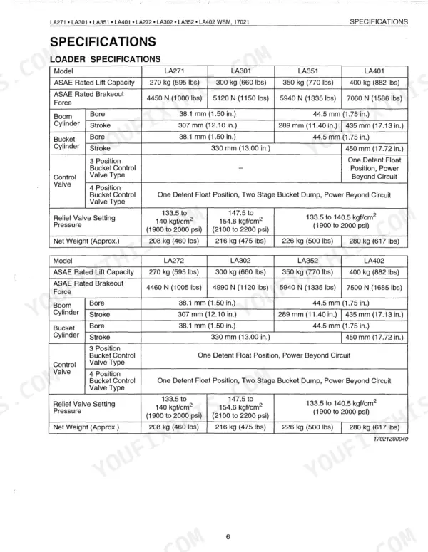
| Specifications | 9-12 | Loader Specifications, Bucket Specifications, Operating Dimensions, Performance Ratings (No Load) |
| Features | 15 | Front Loader Features, Loader Attachment Points, Bucket Control |
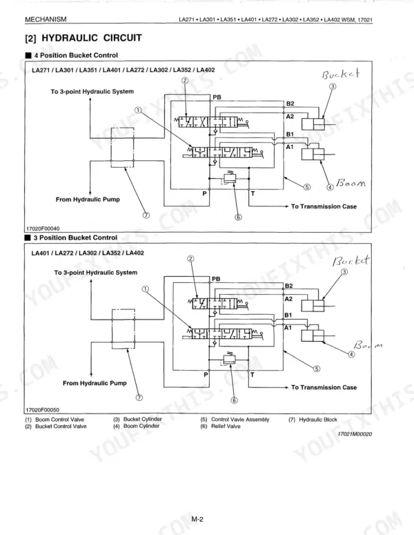
| Hydraulic Circuit | 16 | 3-Position Bucket Control Valve, 4-Position Bucket Control Valve, Boom Cylinders, Relief Valve, Fluid Routing |
| Control Valve Assembly | 17-36 | Control Valve Assembly LA271 LA301 LA351, Control Valve Assembly LA401 LA272 LA302 LA352 LA402, Valve Disassembly, Valve Inspection, Valve Assembly |
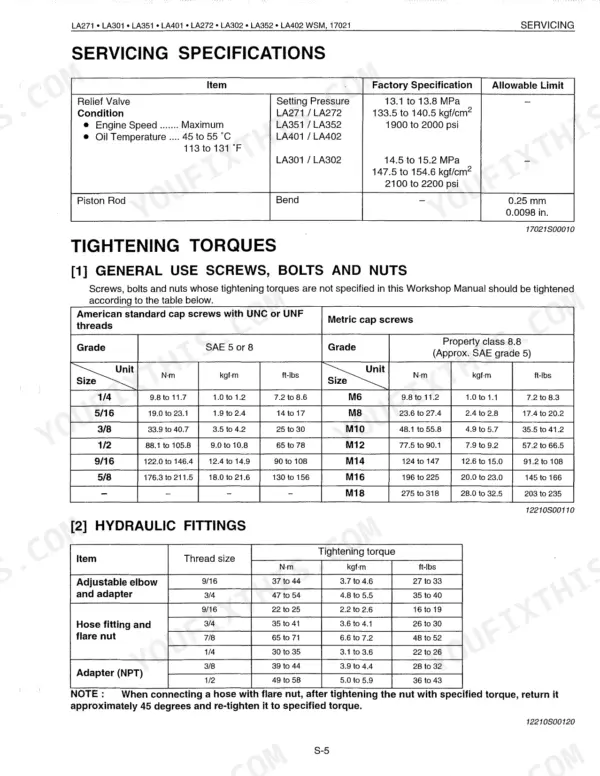
| Relief Valve | 37-38 | Relief Valve Disassembly, Relief Valve Inspection, Relief Valve Assembly, Pressure Setting |
| Boom Cylinder and Bucket Cylinder | 39-40 | Boom Cylinder Disassembly, Bucket Cylinder Disassembly, Piston Mounting Nut Torque Specification |
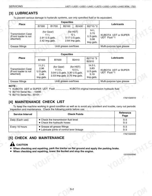
| Servicing | 41-62 | Identification, Lubricants, Maintenance Check List, Check and Maintenance, Check Points of Each Use or Daily, Check Points of Every 10 Hours, Troubleshooting |
Quick Reference Specifications
| Specification | Value | Page |
|---|---|---|
| LA271, LA301, LA351, LA272, LA302, LA352 | ||
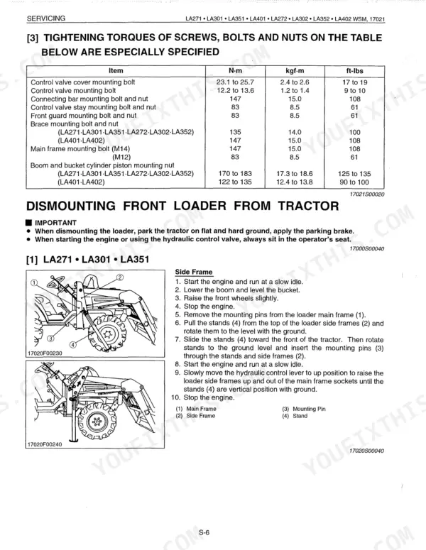
| Boom and bucket cylinder piston mounting nut (LA271, LA301, LA351, LA272, LA302, LA352) | 170 to 183 N-m (125 to 135 ft-lbs) | p. 48 |
| Brace mounting bolt and nut (LA271, LA301, LA351, LA272, LA302, LA352) | 135 N-m (100 ft-lbs) | p. 48 |
| All Models | ||
| Control valve cover mounting bolt | 23.1 to 25.7 N-m (17 to 19 ft-lbs) | p. 48 |
| Control valve mounting bolt | 12.2 to 13.6 N-m (9 to 10 ft-lbs) | p. 48 |
| Connecting bar mounting bolt and nut | 147 N-m (108 ft-lbs) | p. 48 |
| Control valve stay mounting bolt and nut | 83 N-m (61 ft-lbs) | p. 48 |
| Front guard mounting bolt and nut | 83 N-m (61 ft-lbs) | p. 48 |
| Main frame mounting bolt (M14) | 147 N-m (108 ft-lbs) | p. 48 |
| LA401, LA402 | ||
| Boom and bucket cylinder piston mounting nut (LA401, LA402) | 122 to 135 N-m (90 to 100 ft-lbs) | p. 48 |
| Brace mounting bolt and nut (LA401, LA402) | 147 N-m (108 ft-lbs) | p. 48 |
| LA271, LA272, LA351, LA352, LA401, LA402 | ||
| Relief Valve Setting Pressure (High Flow Models) | 13.1 to 13.8 MPa | p. 47 |
| LA301, LA302 | ||
| Relief Valve Setting Pressure (Standard Flow Models) | 14.5 to 15.2 MPa | p. 47 |