


Part of the Kubota Repair Manuals.
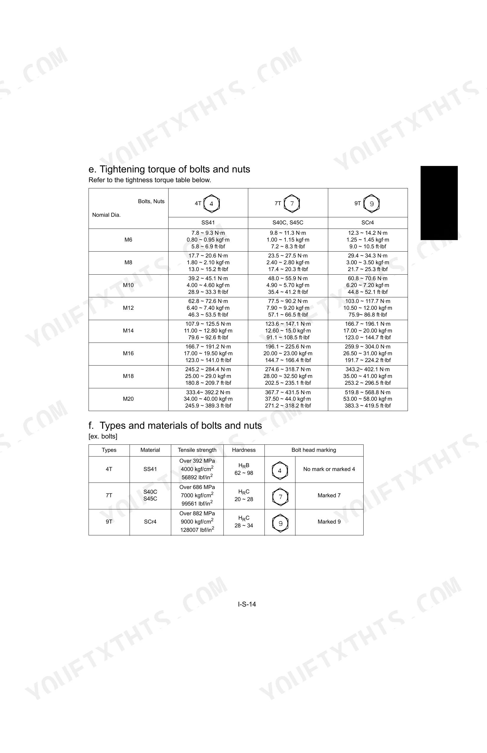
Looking for factory service data on your Kubota U35 compact excavator? This 273-page workshop manual (OEM #97899-60640) documents the U35 and U35-3, with noted compatibility for the KX91-3, KX101-3, and U45-3. Hydraulic circuit diagrams trace pilot pressure from pump to control valve. Wiring diagrams and electric circuit layouts cover both U35 and U35-3 harness configurations, backed by hydraulic troubleshooting and electrical fault-tracing flowcharts. Torque specs and exploded views span front attachment, swivel bearing, undercarriage, and engine internals. Set the travel motor relief valve to 58.8–68.6 N·m and snug the 1/8-inch tapered hydraulic joint body to 19.6–29.4 N·m. Every hour your machine sits is money gone. It’s bookmarked by section, so open it on your tablet, walk to the excavator, and get to work.
What's Inside This Kubota U35, U35-3 Manual
| System | Pages | Key Topics |
|---|---|---|
| General | 4-28 | Body and Engine Identification Marks, Safty Precautions for Servicing, Important Safty Process and Critical Functional Process, Maintenance Intervals, Water and Oil Quantity |
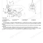
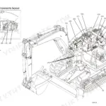
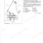
| Machine body(Mechanism Section) | 29-40 | Front Attachment, Greasing Points, Component Interchangeability, Bucket Interchangeability, Arm, Installing Direction of Dust Seal |
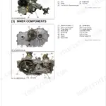
| Machine body(Service Section) | 41-92 | Specifications, Front Attachment, Upper Structure, Swivel Bearing Installation, Cab Glass Replacement Procedure, Under Carriage |
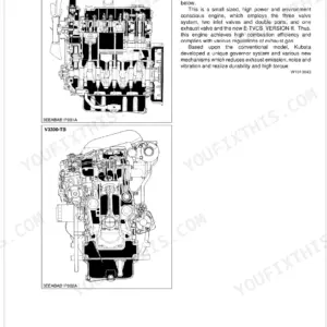
| Engine | 93-102 | Engine Mount, Radiator, Muffler, Pump Coupling, Fuel Hoses, Engine Overhaul |
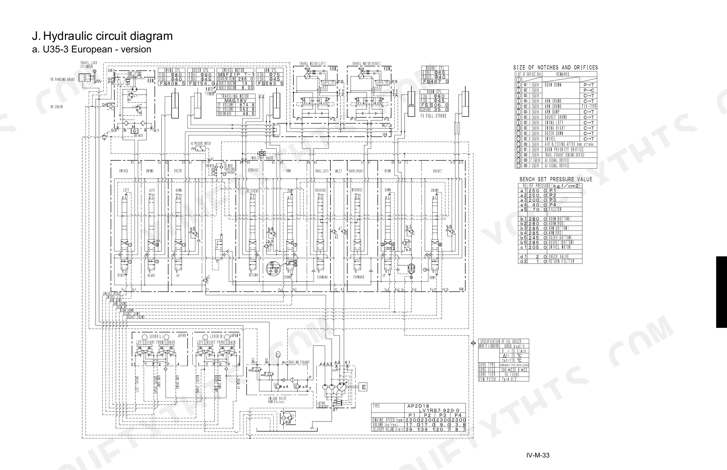
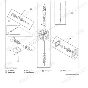
| Hydraulic system(Mechanism Section) | 103-138 | Features of Hydraulic System, Hydraulic System Specifications, Main Pump, Control Valve, Pilot Valve, Hydraulic Circuit Diagram |
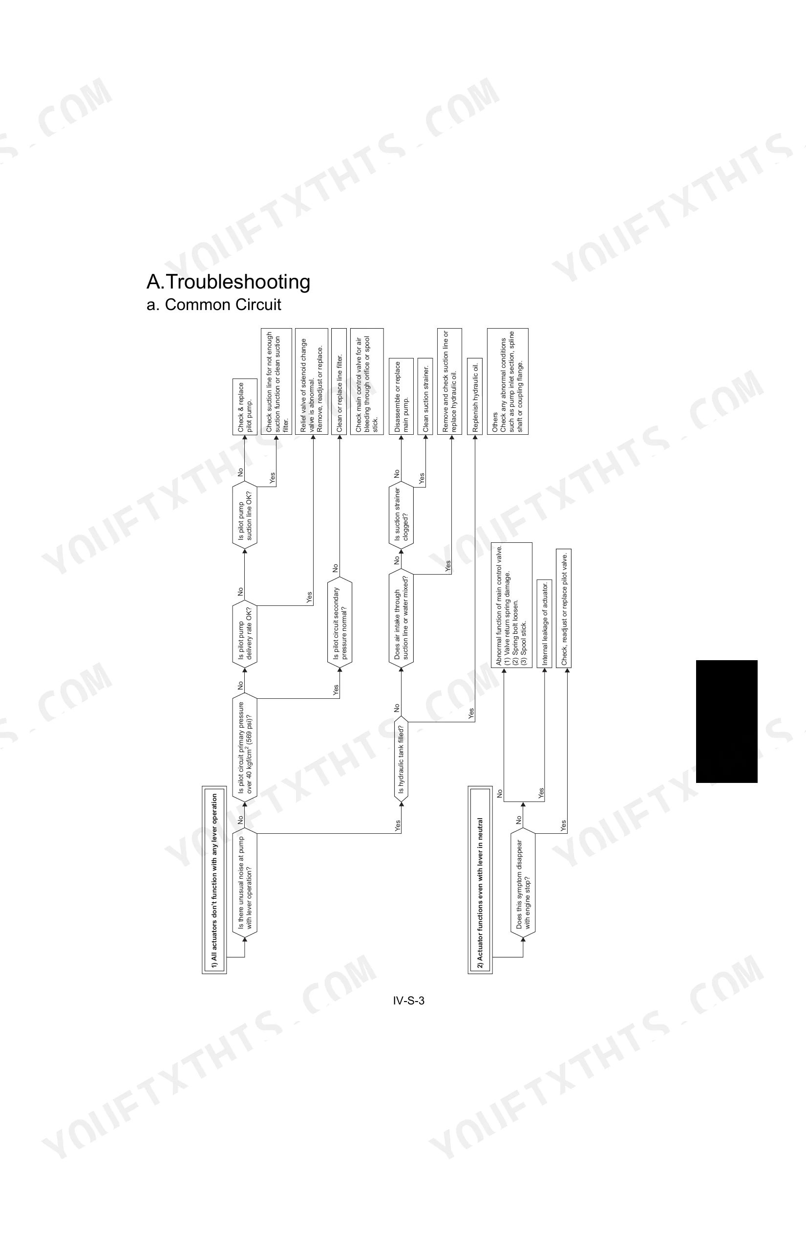
| Hydraulic system(Service Section) | 139-190 | Troubleshooting, Specifications, Testing Instruments & Special Tools, Pump Flow, Pilot Pressure, Disassembling and Assembling |
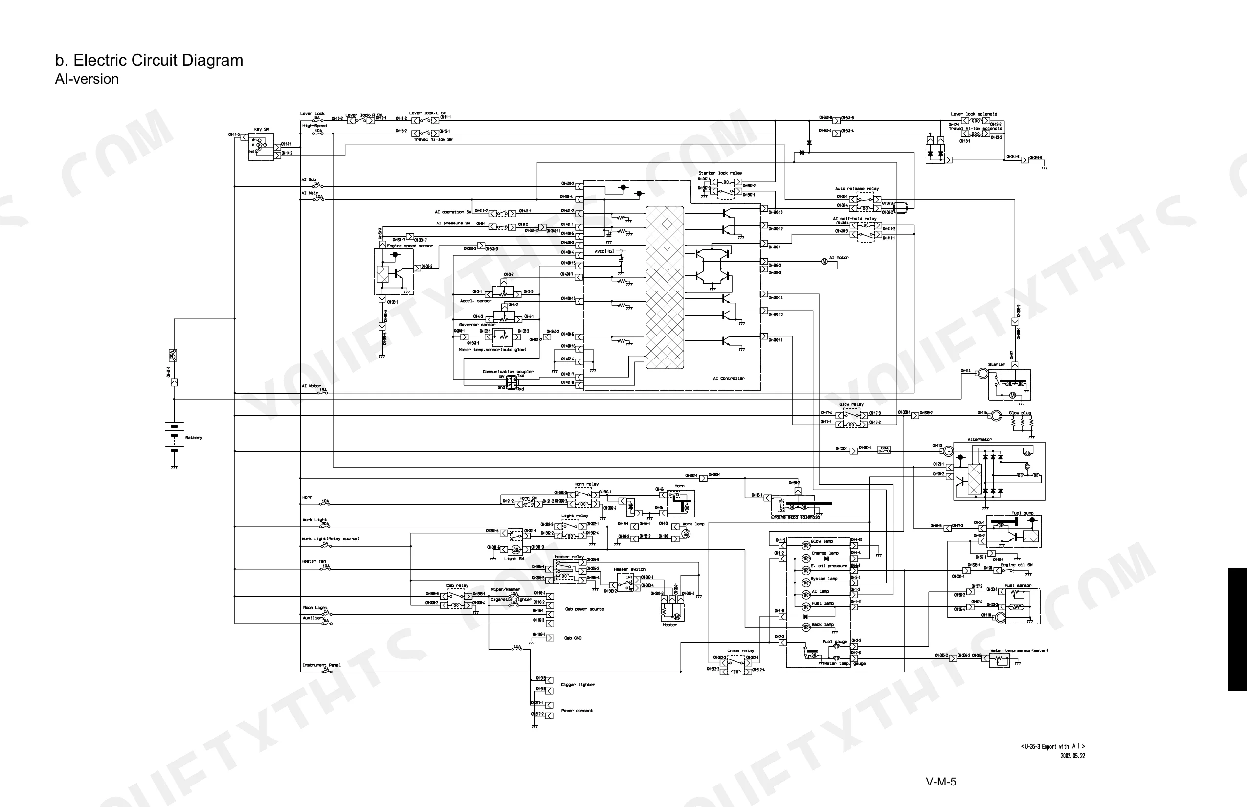
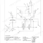
| Electrical system(Mechanism Section) | 191-200 | A. Components and Harness Layout : U35, U35-3, B. Electric Circuit Diagram, C. Electric Wiring Diagram |
| Electrical system(Service Section) | 201-273 | Electrical Equipment Specifications, Wire Harness Installation, Troubleshooting, Troubleshooting Flow Chart, Engine Electrical System, Auto Idle System |
Quick Reference Specifications
| Specification | Value | Page |
|---|---|---|
| Travel motor relief valve tightening torque | 58.8 ~ 68.6 N·m (6.0 ~ 7.0 kgf·m) | p. 129 |
| Travel motor plug tightening torque | 58.8 ~ 68.6 N·m (6.0 ~ 7.0 kgf·m) | p. 129 |
| Hose screw tightening torque (1/8" Union nut section) | 7.8 ~ 11.8 N·m (0.8 ~ 1.2 kgf·m) | p. 15 |
| Joint bodies tightening torque (1/8" R (tapered thread)) | 19.6 ~ 29.4 N·m (2.0 ~ 3.0 kgf·m) | p. 15 |
| Starter switch nut tightening torque | 4.0 ~ 5.0 N·m (0.4 ~ 51 kgf·m) | p. 207 |
| Slow-blow fuse rating | 60A | p. 212 |
| Starter motor nominal voltage | 12 V | p. 203 |
| Starter motor nominal output | 1.4 kW | p. 203 |
| Glow plug resistance (at 20 °C) | 10 Ω | p. 203 |
| Glow plug tightening torque (Body: M10 × 1.25) | 20 ~ 25 N·m (2.0 ~ 2.5 kgf·m) | p. 203 |
| Coupler insertion pulling force (to check tightness) | 29.7 N (3 kg) or less force | p. 210 |
| Control box harness wiring clamp clearance | 200 mm up to the clamp | p. 211 |
Kubota U35, U35-3 Common Problems This Manual Covers
Kubota U35 engine cranks but will not start, no ignition after multiple key cycles
Check the 60A slow-blow fuse (page 212) before anything else. Verify battery voltage reaches the starter S-terminal with a circuit tester; if voltage is absent, trace the harness back to the key switch. Torque the cable-to-starter terminal nut to 5.9~11.8 N·m (page 207) and inspect all earth connections at the starter body for corrosion or looseness.
Manual Section: Electrical System Troubleshooting: Starter, Auto Release, Electronic Accelerator, Auto Glow, AI System p. 212Starter turns over slowly or won't engage, weak crank on key turn
Measure battery voltage under load. The battery rated at 55 Ah (page 203) should hold charge through the full crank cycle. Clean the negative cable earth connection to the frame, then trace the earth line for corrosion or breaks. Test the starter switch for continuity and inspect the harness for a broken wire between the switch and the starter S-terminal.
Manual Section: Electrical System Troubleshooting: Starter, Auto Release, Electronic Accelerator, Auto Glow, AI System p. 203Glow plug circuit resistance out of spec, cold start attempts fail or run rough
Remove each glow plug and measure resistance at 20°C. A healthy plug reads 10 Ω; anything well outside that range requires replacement (page 203). Torque new plugs to 20~25 N·m on the M10×1.25 body thread. Test the glow plug wiring harness for open circuits or shorts before reinstalling the plugs.
Manual Section: Electrical System Troubleshooting: Starter, Auto Release, Electronic Accelerator, Auto Glow, AI System p. 203Intermittent electrical failures spread across multiple cab circuits, several functions randomly dead
Inspect each harness coupler in the affected circuit, pulling firmly to confirm proper seating. Any coupler that releases with 29.7 N (3 kg) or less force is not locked correctly (page 210). Verify the control box harness has 200 mm of free wire before the first clamp (page 211). Test suspect wire segments for continuity and probe for line-to-ground shorts.
Manual Section: V. Electrical system(Service section) p. 210All hydraulic actuators not responding, boom, bucket, and travel dead after engine start
Verify hydraulic oil level; full capacity is 55.0 L (page 12) and oil should be changed every 1000 hours (page 9). Confirm the safety lever is disengaged, then work through the common-circuit troubleshooting chart. If all actuators are dead with the lever released, the fault is upstream in the pump output or pilot pressure circuit.
Manual Section: Hydraulic System Troubleshooting: Common CircuitFrequently Asked Questions
How do I reset the Kubota U35 / U35-3 error codes?
Enter the service mode: disconnect the 8-pin coupler, turn the AI operation switch OFF, then turn the key switch ON. Open the "Fail record delete menu (7)" and toggle the AI operation switch ON and OFF. This deletes the fail record, and the AI operation lamp (green) blinks 11 times to confirm. p. 263
What does the Kubota U35 / U35-3 error code mean?
The system lamp signals error codes by blinking in operating mode. An "Acceleration sensor line break" shows 2 blinks; a "Governor sensor line break" shows 3. The manual explains each fail symptom in detail, such as "Water temperature sensor defective" for a "Water temperature sensor line break". p. 258
How do I perform the self-diagnostic test on a Kubota U35-3?
Start by entering the service mode. Disconnect the 8-pin coupler from the AI controller, set the AI operation switch to OFF, then turn the key switch to ON or start the engine. From there you can reach the diagnostic menus, such as the "Trouble indicator lamp menu for usual control" and "Engine speed sensor check menu". p. 259
How do I clear the panel alarm on a Kubota U35-3?
The panel alarm is tied to stored fail records, so clearing it means a trip through the service mode. Open the "Fail record delete menu (7)", then switch the AI operation switch ON and OFF to wipe the records. The AI operation lamp (green) blinks 11 times once all fail records are gone. p. 263
What do I get after purchasing this Kubota U35, U35-3 manual?
Immediate download of the complete 273-page searchable Workshop Manual. Open it on any device, whether that's the laptop at your desk or the phone in the field.
Is this Kubota U35, U35-3 Workshop Manual printable?
Yes, print as many copies as you want, with no restrictions. Plenty of mechanics print just the section they need and carry it to the shop floor.
Does this Kubota U35, U35-3 Workshop Manual have electrical diagrams?
Yes. Full electrical schematics are included, with wire colors, connector locations, and circuit descriptions.


Reviews
There are no reviews yet.