Part of the Kubota Repair Manuals.
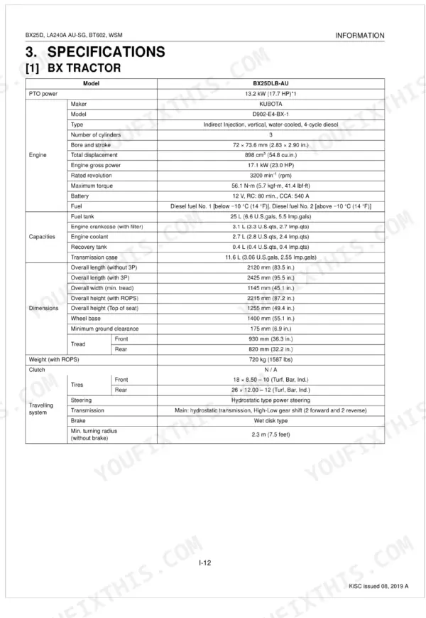
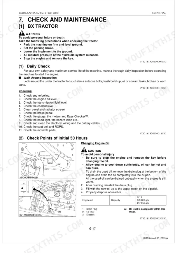
This Kubota Shop Manual (publication 9Y111-11322) is the factory service reference for the BX25DLB-AU sub-compact tractor and its matched attachments, the LA240A AU-SG front loader and the BT602 backhoe, built from 2014 to 2019. The 411-page PDF splits each system into structure and servicing so you understand the machine before you take it apart.
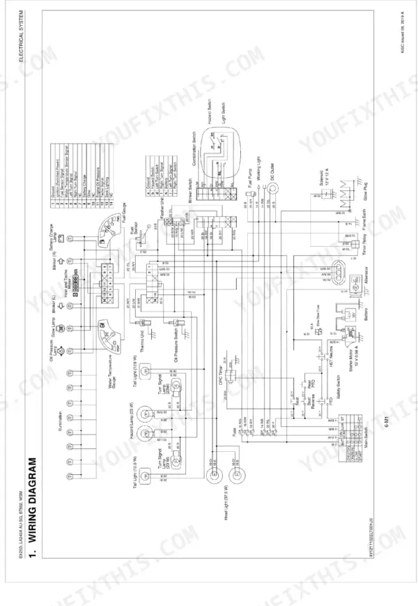
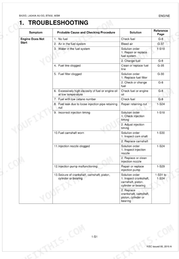
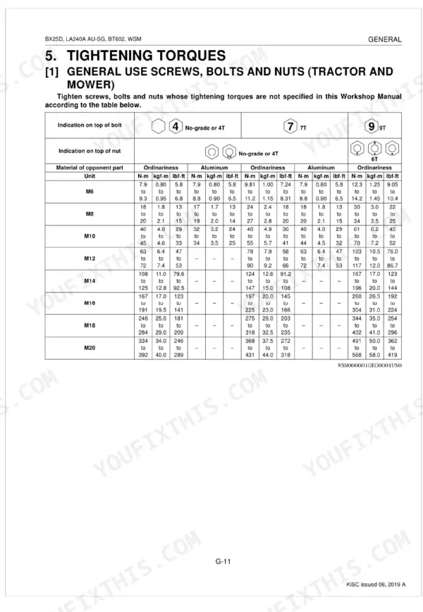
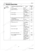
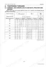
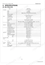
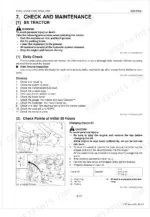
It covers the engine, transaxle and hydrostatic drive, front axle, steering, hydraulics, the electrical system with wiring diagrams, and both the front loader and backhoe. Every servicing chapter carries troubleshooting charts, servicing specifications, tightening torques, and step-by-step disassembly and assembly.
Whether you are diagnosing a no-start interlock, adjusting the HST pedal, testing the battery and starter, or setting backhoe cylinder torques, this manual gives the exact Kubota procedures a BX25DLB-AU owner or mechanic needs.
What's Inside This Manual
| System | Pages | Key Topics |
|---|---|---|
| General | Identification, Handling Precautions for Electrical Parts and Wiring, Lubricants, Fuel and Coolant (Bx Tractor, Front Loader, Backhoe) | |
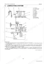
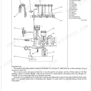
| Engine | Lubricating System, Cooling System, Fuel System | |
| Engine Servicing | Engine Body, Lubricating System, Cooling System, Fuel System, Cylinder Head, Valves | |
| Transaxle | Structure, Traveling System (Hydrostatic Transmission, Range Gear Shift Section, Front Wheel Drive Section, Differential Gear Section, Brake Section) | |
| Transaxle Servicing | Hydrostatic Transmission, Hydraulic Cylinder, Transaxle, PTO Clutch, Differential, Brake | |
| Front Axle | Structure, Camber, Kingpin Angle, Caster, Toe-In | |
| Front Axle Servicing | Power Steering Cylinder, Bevel Gear Case, Front Gear Case, Differential Gear | |
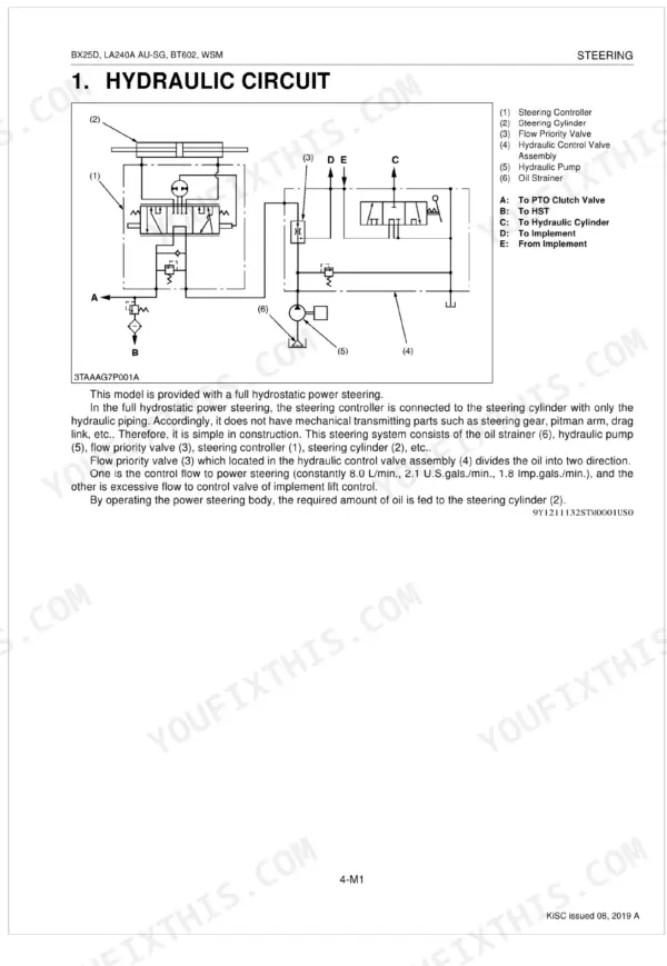
| Steering | Hydraulic Circuit, Steering Controller, Steering Cylinder | |
| Steering Servicing | Relief Valve, Steering Controller, Power Steering Cylinder, Tie-Rod, Meter Panel | |
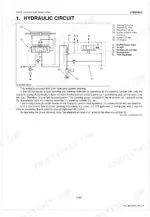
| Hydraulic System | Hydraulic Circuit, Hydraulic Pump, Control Valve, Flow Priority Valve, Relief Valve, Hydraulic Cylinder, Hydraulic Block Type Outlet, Mower Linkage | |
| Hydraulic System Servicing | Relief Valve, Hydraulic Pump, Mower Lift Linkage, Hydraulic Cylinder, Control Valve | |
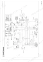
| Electrical System | Wiring Diagram, Starting System (Main Switch Position, Safety Switch, Operator Presence Control), Charging System (Electrical Circuit, Ic Regulator), Lighting System | |
| Electrical System Servicing | Battery, Main Switch, Starter, Glow Plug, Safety Switch, Fuel Pump, Alternator | |
| Front Loader | Hydraulic Circuit Schematic, Control Valve Assembly, Boom Cylinder and Bucket Cylinder, Relief Valve | |
| Front Loader Servicing | Spill Guard, Bucket, Boom, Hydraulic Cylinders, Side Frames, Main Frames | |
| Backhoe | Hydraulic Circuit, Control Valve (Structure, Operation, Overload Relief Valve), Hydraulic Cylinder | |
| Backhoe Servicing | Control Valve, Boom, Dipperstick, Bucket, Swing Cylinder, Stabilizer Cylinder |
Documents This Manual Refers To
The manufacturer cites these publications by number. We carry them:
Quick Reference Specifications
| Specification | Value | Page |
|---|---|---|
| Boom cylinder head torque | 350 to 400 N-m | p. 396 |
| Dipperstick cylinder, stabilizer cylinder head torque | 250 to 280 N-m | p. 396 |
| Battery Voltage (Factory Specification) | More than 12 V | p. 309 |
| Battery Potential Difference (Allowable Limit) | Less than 0.1 V | p. 309 |
| Battery Terminal Connection Potential difference (Allowable Limit) | Less than 0.1 V | p. 312 |
| Starter Commutator O.D. (Factory Specification) | 30.0 mm | p. 309 |
| Starter Commutator O.D. (Allowable Limit) | 29.0 mm | p. 309 |