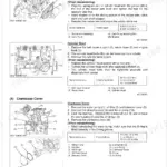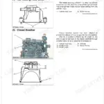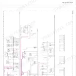


Part of the Kubota Repair Manuals.
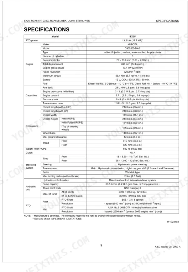
This Kubota Workshop Manual (publication 9Y111-01970) is the factory service reference for the BX25 sub-compact tractor with its LA240 front loader, BT601 backhoe, and the RCK54, RCK54P, and RCK60B rotary mower decks. Built around the D902-E3-BX-2 diesel engine, the 427-page PDF follows Kubota's Mechanism and Servicing layout.
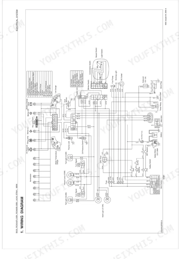
It documents the engine, transaxle and hydrostatic drive, front axle, steering, hydraulic system, and the full electrical system with wiring diagrams, plus dedicated chapters for the rotary mower, front loader, and backhoe. You get troubleshooting, servicing specifications, tightening torques, continuity checks, and disassembly and assembly steps.
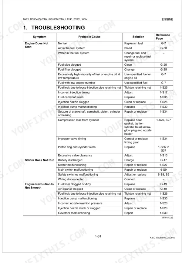
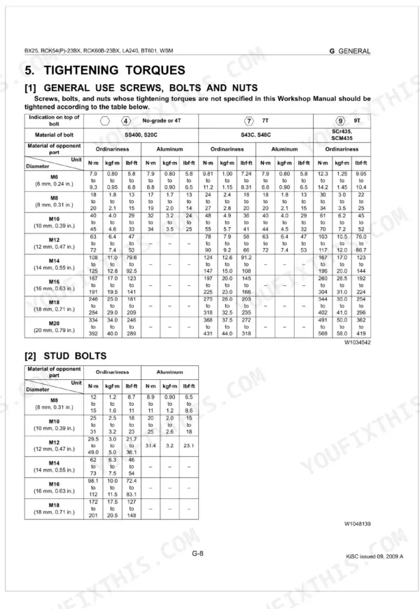
Owners and independent mechanics reach for it to solve a no-start, restore weak loader lift, service the mower deck, or set the correct wheel and blade torques using numbers taken directly from Kubota.
What's Inside This Manual
| System | Pages | Key Topics |
|---|---|---|
| General | Tractor Identification, Wiring, Battery, Fuse, Connector, Handling of Circuit Tester, Lubricants Fuel and Coolant | |
| Engine | Lubricating System, Cooling System, Fuel System | |
| Transaxle | Travelling System, Hydrostatic Transmission, Range Gear Shift Section, Front Wheel Drive Section, Differential Gear Section, Brake Section, PTO System, PTO Clutch and Valve | |
| Front Axle | Front Wheel Alignment, Camber, Kingpin Angle, Caster, Toe-In, Checking, Disassembling and Servicing | |
| Steering | Hydraulic Circuit, Steering Controller, Steering Cylinder | |
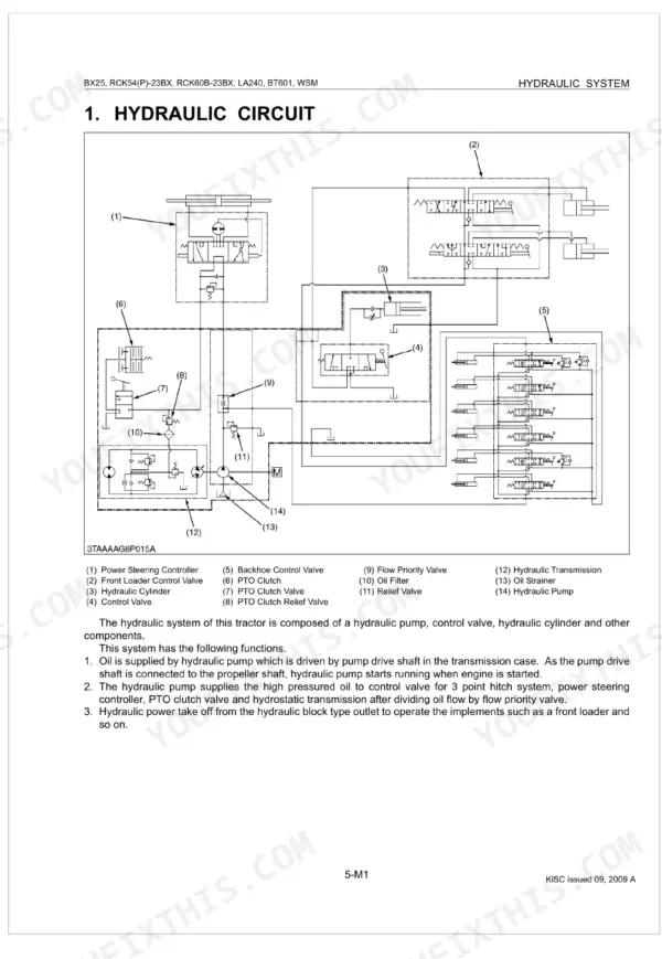
| Hydraulic System | Hydraulic Circuit, Hydraulic Pump, Control Valve, Flow Priority Valve, Relief Valve, Hydraulic Cylinder, Hydraulic Block Type Outlet, Mower Linkage | |
| Electrical System | Wiring Diagram, Starting System, Main Switch Position, Safety Switch, Operator Presence Control (Opc), Charging System, Electrical Circuit, Ic Regulator (3P Connector Type) | |
| Rotary Mower | Power Transmission, Lifting Mechanism, Self-Balancer System | |
| Front Loader | Hydraulic Circuit, Control Valve Assembly, Boom Cylinder and Bucket Cylinder | |
| Backhoe | Safety Decals, Backhoe Terminology, Operating Dimensions, Digging Force (per Sae J49), Cycle Time (Seconds), Hydraulic Cylinders, Bucket Sizes, Lift Capacity (per Sae J31) |
Documents This Manual Refers To
The manufacturer cites these publications by number. We carry them:
Quick Reference Specifications
| Specification | Value | Page |
|---|---|---|
| Relief valve readjustment pressure range | 15.0 to 20.0 MPa (153 to 203 kgf/cm², 2180 to 2900 psi) | p. 164 |
| Bevel gear case mounting screw (M12) torque | 77.5 to 90.2 N·m (7.9 to 9.2 kgf·m, 57.2 to 66.5 ft-lbs) | p. 205 |
| Front gear case cover mounting screw torque | 48.1 to 55.8 N·m (4.9 to 5.7 kgf·m, 35.5 to 41.2 ft-lbs) | p. 205 |
| Transmission oil filter replacement interval | Initial 50 hours, Every 200 hours | p. 25 |
| Fuel filter element check interval | Every 100 hours | p. 25 |
| Fuel filter element replacement interval | Every 500 hours | p. 25 |
| Battery type | 526RA | p. 32 |
| Battery voltage | 12 V | p. 32 |
| Main switch continuity (OFF Position, B terminal - ACC terminal) | Infinity | p. 287 |
| Main switch continuity (OFF Position, B terminal - ST terminal) | Infinity | p. 287 |
| Main switch continuity (OFF Position, B terminal - G terminal) | Infinity | p. 287 |
| Main switch continuity (ON Position, B terminal - ACC terminal) | 0 Ω | p. 287 |