

Part of the Kubota Repair Manuals.
This is the Kubota Workshop Manual for the BX24 tractor and its matched attachments: the LA240 front loader, the BT601 backhoe, and the RCK54, RCK54P, and RCK60B rotary mowers. It is a 421 page PDF (OEM number 97897-18200) built around the D902-E2-BX-2 diesel engine, covering the whole tractor plus every implement in one document.
Sections run through the engine, transaxle, front axle, steering, hydraulic system, and electrical system, then continue into the rotary mower, front loader, and backhoe. Each is split into general, mechanism, and servicing so you can understand a system before troubleshooting, disassembling, and reassembling it.
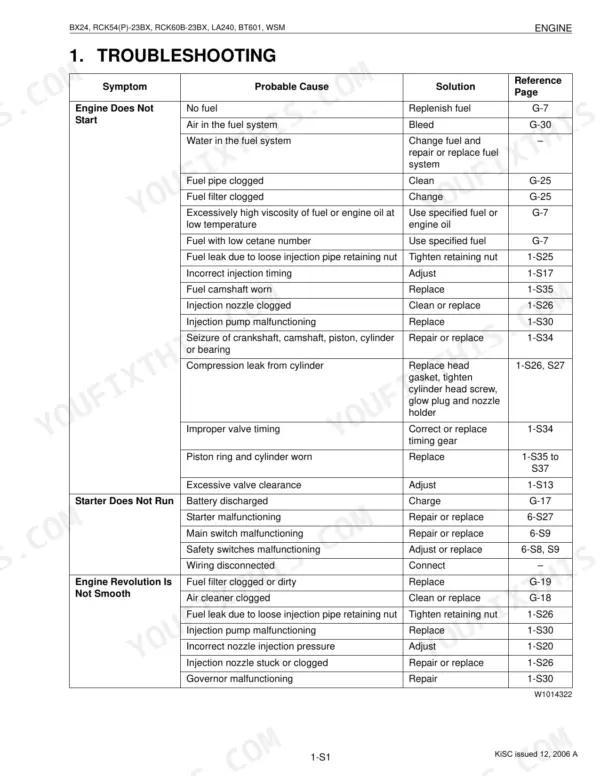
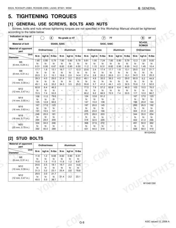
Use it to diagnose no-start and shutdown faults, weak hydraulics, and mower or loader problems, and to set fasteners such as the front wheel screws to 149.2 to 179.0 N-m. Instant PDF download, print the pages you need.
What's Inside This Manual
| System | Pages | Key Topics |
|---|---|---|
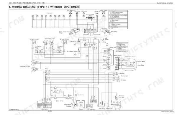
| G General | 12-59 | Tractor, Electrical Parts, Wiring, Battery, Fuse, Connector, Lubricants, Fuel |
| Engine | 60-124 | Lubricating System, Cooling System, Fuel System, Cylinder Head and Valves, Piston and Connecting Rod, Crankshaft |
| Transaxle | 125-192 | Hydrostatic Transmission, Range Gear Shift Section, Front Wheel Drive Section, Differential Gear Section, Brake Section, PTO System |
| Front Axle | 193-212 | Structure, Front Wheel Alignment, Differential Case, Differential Pinion Shaft, Bevel Pinion Shaft, Center Pin |
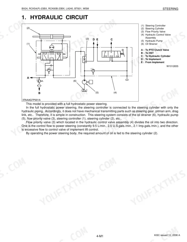
| Steering | 213-227 | Hydraulic Circuit, Steering Controller, Steering Cylinder, Relief Valve, Power Steering Controller, Power Steering Cylinder |
| Hydraulic System | 228-258 | Hydraulic Circuit, Hydraulic Pump, Control Valve, Flow Priority Valve, Relief Valve, Hydraulic Cylinder |
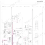
| Electrical System | 259-306 | Wiring Diagram, Starting System, Charging System, Lighting System, Gauges, DC Outlet |
| Rotary Mower | 307-344 | Power Transmission, Lifting Mechanism, Self-Balancer System, Mower Blade, Gear Box, Universal Joint |
| Front Loader | 345-372 | Hydraulic Circuit, Control Valve Assembly, Boom Cylinder, Bucket Cylinder, Side Frames, Front Guard |
| Backhoe | 373-421 | Hydraulic Circuit, Control Valve, Control Valve Structure, Control Valve Operation, Control Valve Overload Relief Valve, Hydraulic Cylinder |
Quick Reference Specifications
| Specification | Value | Page |
|---|---|---|
| BX24 | ||
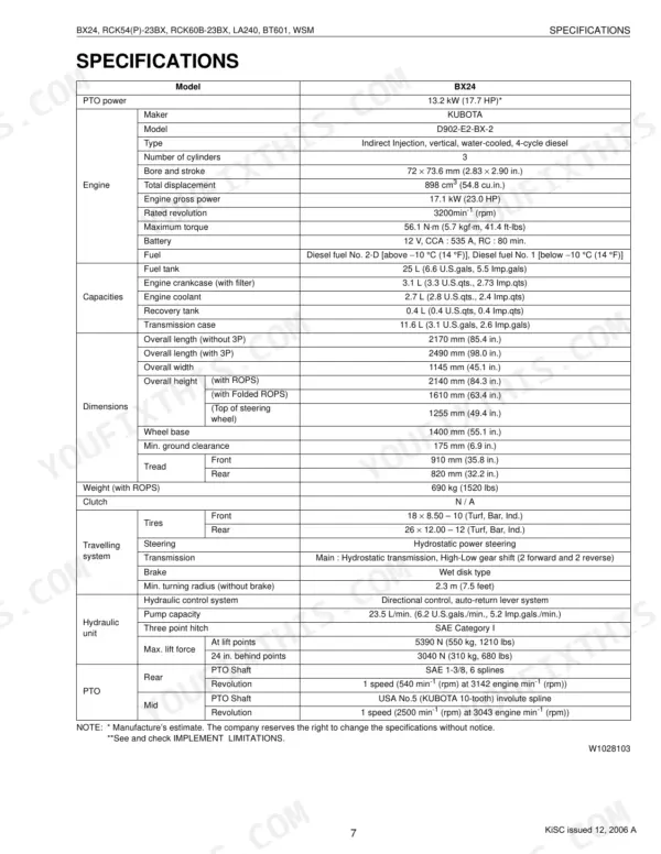
| Front wheel mounting screws torque | 149.2 to 179.0 N·m (15.2 to 18.3 kgf·m, 110 to 132 ft-lbs) | p. 28 |
| Rear wheel mounting screws torque | 108.5 to 130.2 N·m (11.1 to 13.3 kgf·m, 80 to 96 ft-lbs) | p. 28 |
| Fuel filter element replacement interval | Every 500 hours | p. 23 |
| Engine stop solenoid replacement | Replace if defective | p. 278 |
| Battery Voltage | More than 12 V | p. 283 |
| Battery CCA | 535 A | p. 22 |
| Solenoid fuse capacity | 15 A | p. 44 |
| Hazard fuse capacity | 15 A | p. 44 |
| Seat switch number of contacts | 1 | p. 266 |
| RCK54-23BX, RCK60B-23BX | ||
| Mower blade screw torque (RCK54-23BX, RCK60B-23BX) | 102.9 to 117.7 N·m (10.5 to 12.0 kgf·m, 75.9 to 86.8 ft-lbs) | p. 335 |
| RCK54P-23BX | ||
| Mower blade screw torque, RCK54P-23BX | 103 to 118 N·m (10.5 to 12.0 kgf·m, 76 to 87 ft-lbs) | p. 335 |
| RCK54-23BX, RCK60B-23BX, RCK54P-23BX | ||
| Pulley boss mounting nut torque | 23.5 to 27.4 N·m (2.4 to 2.8 kgf·m, 17.4 to 20.3 ft-lbs) | p. 335 |