


Part of the Kubota Repair Manuals.
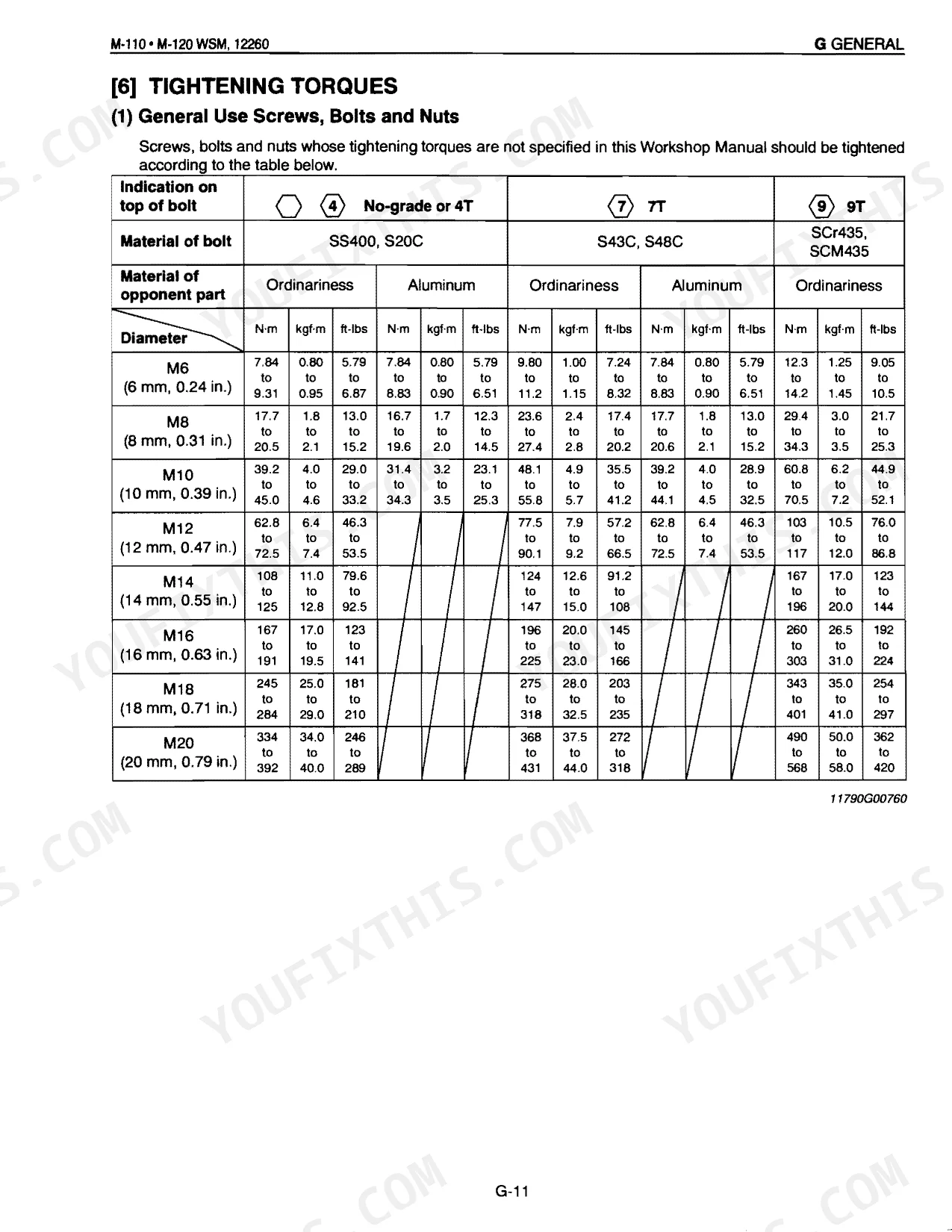
Both M-110 and M-120 variants are documented end to end here: engine and turbocharger, power shift transmission, rear axle, hydraulics, electrical, and cab. Wiring diagrams trace every circuit; hydraulic schematics map the three-point hitch and power steering. Mechanics get exploded views and step-by-step procedures. The electrical section lists pinout data for each connector in the power shift circuit, with troubleshooting charts and service intervals running from the initial 50-hour check out to 3000 hours. Cylinder head screws torque to 127.5–137.3 N·m (94–101 ft-lbs), and the fuel filter gets swapped at 50 hours, then every 200 after. With the tractor down, skip the forum guesswork and pull the factory figure on the first try. Bookmarks and full-text search drop you straight into the system on the bench.
What's Inside This Kubota M-110, M-120 Manual
| System | Pages | Key Topics |
|---|---|---|
| General | 12-77 | Features, Tractor Identification, Handling Precautions for Electrical Parts and Wiring (Battery, Fuse, Connector, Handling of Circuit Tester), Lubricants, Fuel and Cooling Water |
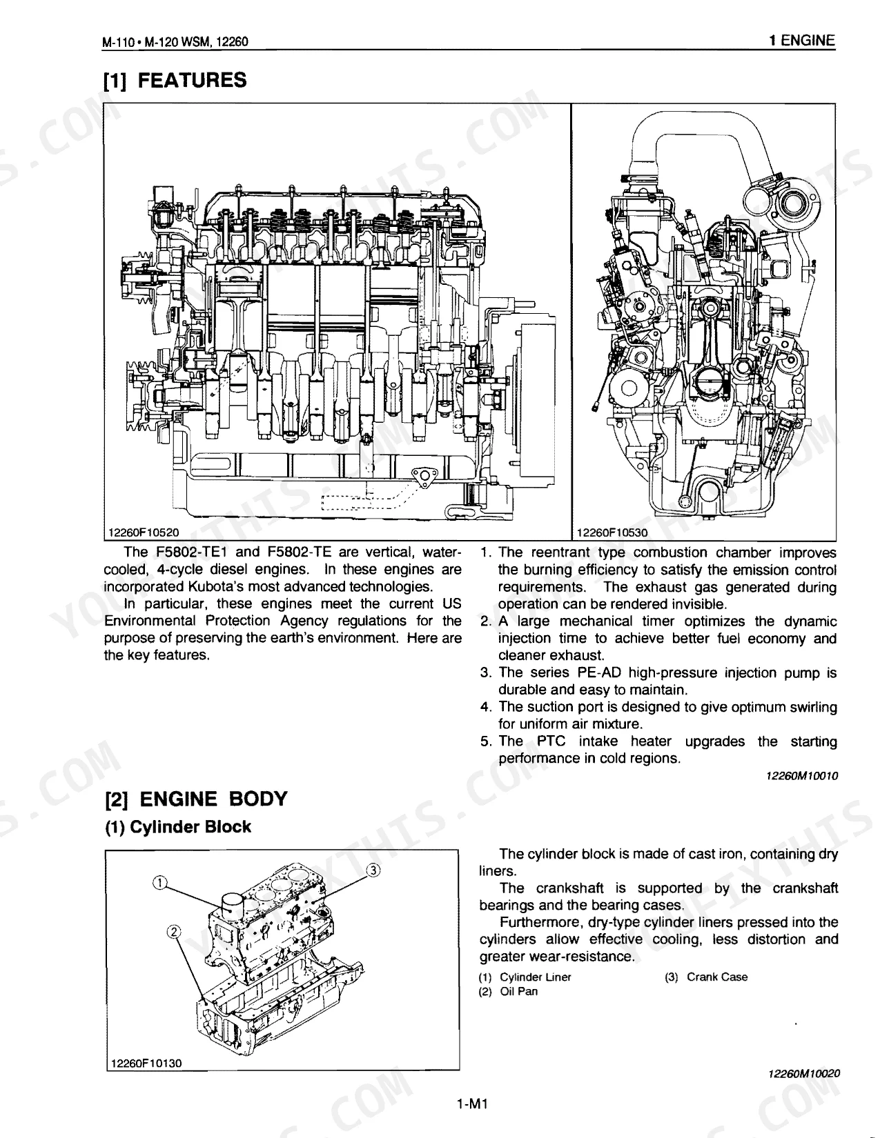
| Sect 1 Engine | 78-171 | Features |
| Sect 2 Clutch | 172-199 | Damper Disc, Hydraulic PTO Clutch, PTO Clutch Valve, PTO Clutch Pack |
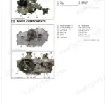
| Sect 3 Transmission | 200-305 | Structure [M-110], Structure [M-120] (Control, Auxiliary Control-Additional Control), Travelling System (Power Shift System) |
| Sect 4 Rear Axle | 306-317 | Planetary Gear, Internal Gear, Brake Shaft, Rear Axle Case, Differential Side Gear, Rear Axle Nut |
| Sect 5 Brakes | 318-343 | Features, Travelling Brake (Operation, Brake Body, Master Cylinder, Equalizer, Brake Oil), Parking Brake |
| Sect 6 Front Axle | 344-385 | Knuckle Shaft, Steering Cylinder, Front Axle Gear Case, Bevel Gear Case, Planetary Gear, Differential Assembly |
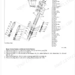
| Sect 7 Steering | 386-417 | Features, Power Steering Hydraulic Circuit, Power Steering System Hydraulic Pump, Steering Controller (Control Valve, Metering Device, Oil Flow), Flow Control Valve |
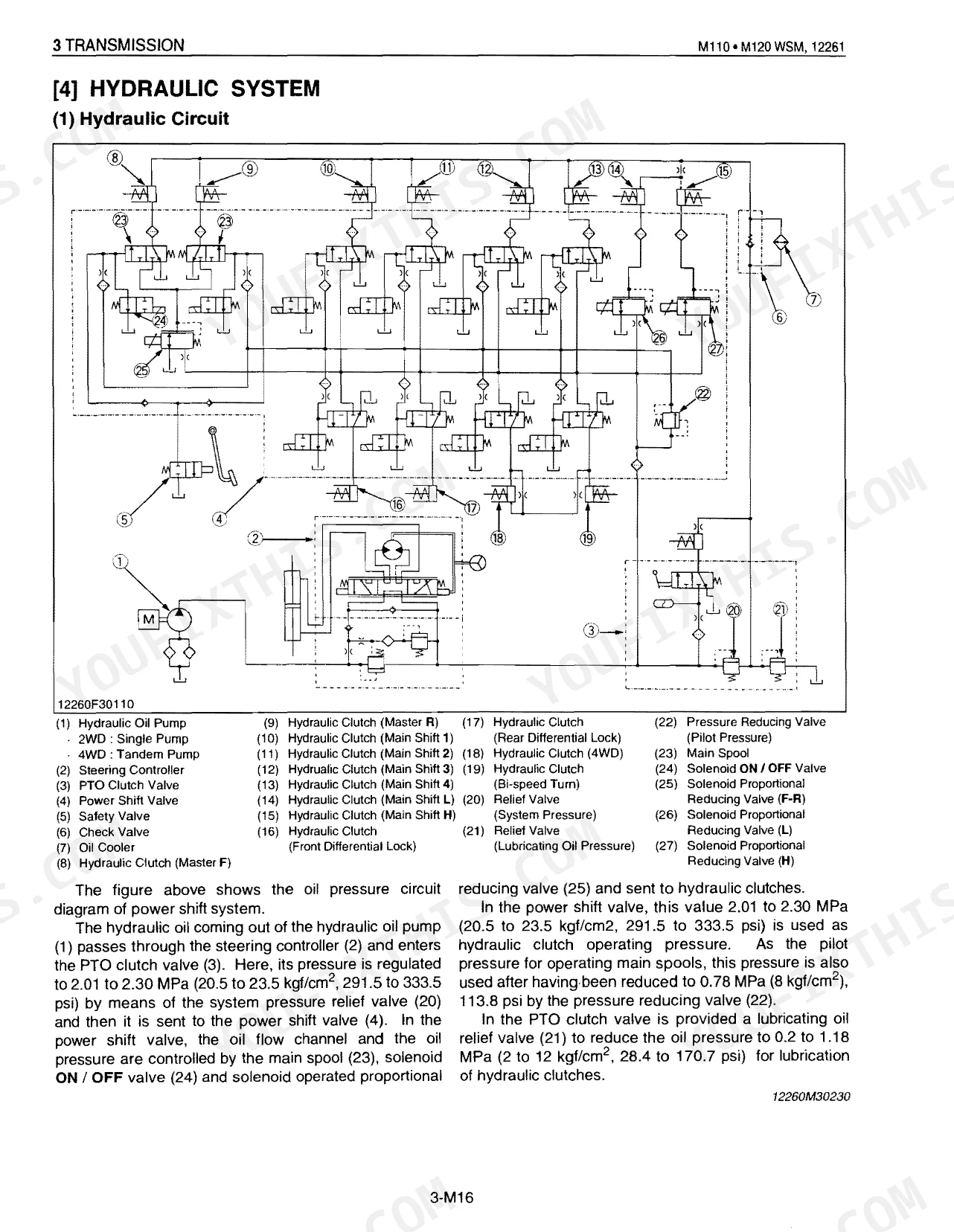
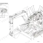
| Sect 8 Hydraulic System | 418-479 | Overall Construction of Hydraulic System, Three Point Hitch System (System Outline, System Construction, Control Outline) |
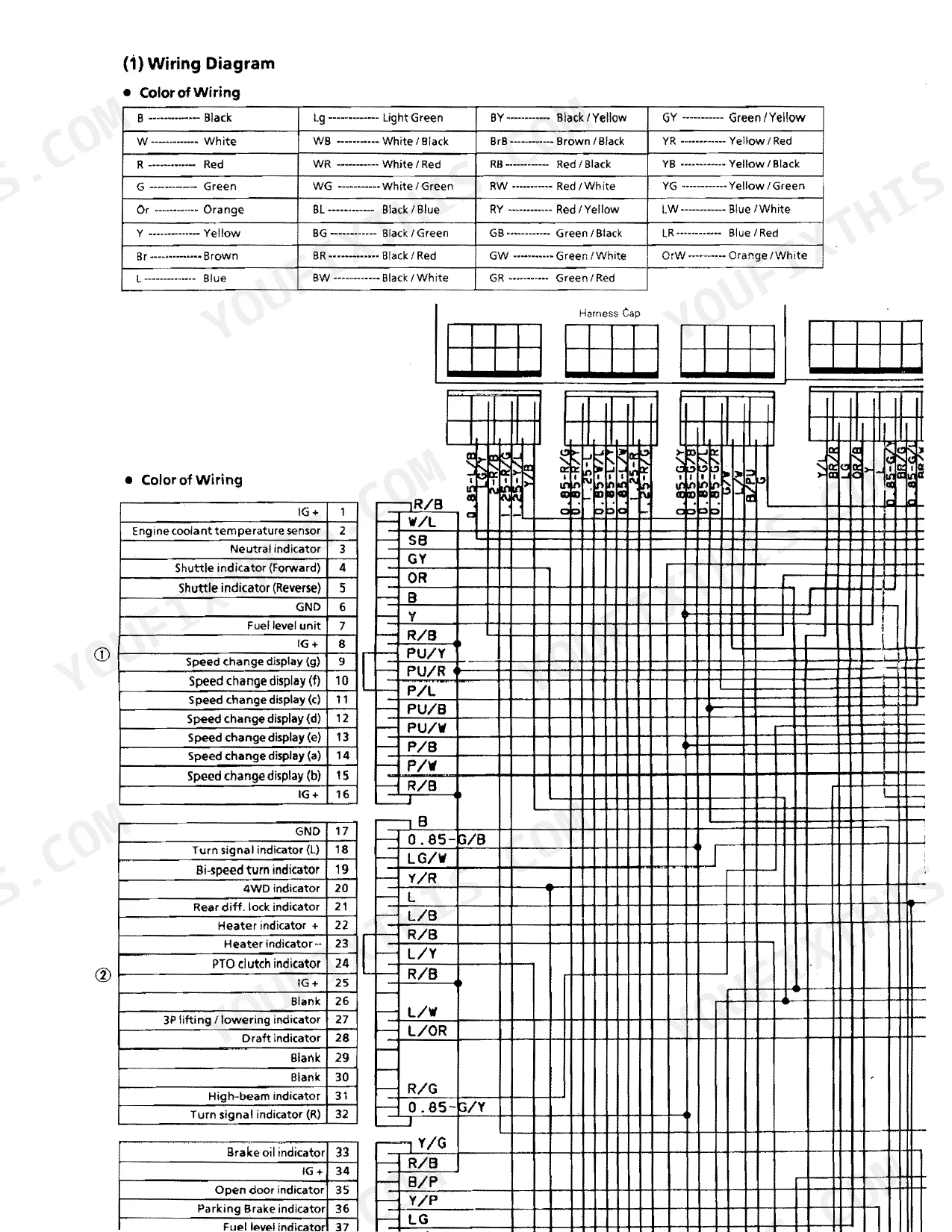
| Sect 9 Electrical | 480-568 | Wiring Diagram, Starting System (Starter Motor, Intake Air Heater, Safety Starting System), Engine Key Switch Shut-Off System (Fuel Control Motor, Operation) |
| Sect 10 Cab | 569-634 | Air Conditioner Component, Refrigeration System, System Control, Electrical System, Front Windshield Wiper, Rear Windshield Wiper |
Quick Reference Specifications
| Specification | Value | Page |
|---|---|---|
| Cylinder head screws torque | 127.5 to 137.3 N·m / 13.0 to 14.0 kgf·m / 94.0 to 101.3 ft-lbs | p. 120 |
| Fuel filter replacement interval | Initial 50 Hours, then every 200 Hours | p. 26 |
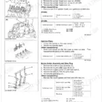
| Fuel pump mounting screw torque | 23.5 to 27.5 N·m / 2.4 to 2.8 kgf·m / 17.4 to 20.3 ft-Ibs | p. 120 |
| Hydraulic pump mounting screw (3 Point hitch pump) torque | 39.2 to 44.1 N·m / 4.0 to 4.5 kgf·m / 28.9 to 32.5 ft-Ibs | p. 458 |
| Hydraulic cylinder assembly mounting screw and nut torque | 77.5 to 90.2 N·m / 7.9 to 9.2 kgf·m / 57.1 to 66.5 ft-Ibs | p. 458 |
| PTO power (Factory observed) | 65.6 kW | p. 8 |
| Total displacement | 5832 cm3 | p. 8 |
| Fuel tank capacity | 150 L | p. 8 |
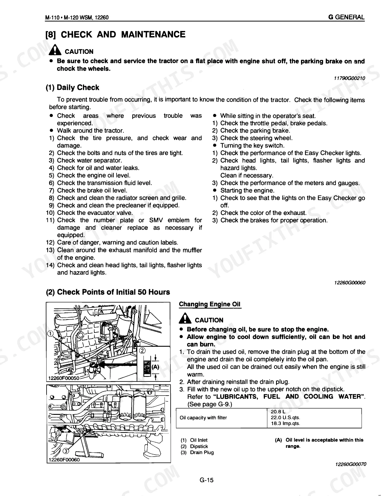
| Engine crankcase capacity | 20.8 L | p. 8 |
| Transmission case capacity | 55 L | p. 22 |
Kubota M-110, M-120 Common Problems This Manual Covers
Kubota M120 3-point hitch will not respond normally and lift light flashes fast at startup.
Test system pressure at the hydraulic pump. The pump should hit its rated 18.6 MPa (2773 psi), as shown on page 456. Then check the 3-point hitch pump mounting screws and torque them to 39.2 to 44.1 N·m (28.9 to 32.5 ft-lbs) per page 458.
Manual Section: Sect 8 Hydraulic System p. 456Engine runs poorly, loses fuel delivery, or must be primed manually after fuel service.
Replace the fuel filter every 200 hours after the initial 50 hours, referencing the schedule on page 26. Tighten the new filter quickly until it contacts the mounting surface, then hand-tighten an additional 1/2 turn only as detailed on page 42. Bleed the fuel system completely.
Manual Section: General p. 26Starter motor does not operate or tractor jolts when shifting the main shift change.
Inspect the transmission wiring harness and connectors against the electrical pinout diagram. If nothing's faulted, run the transmission calibration procedure. On the M-110, drain the transmission case and refill with exactly 55 L of fluid.
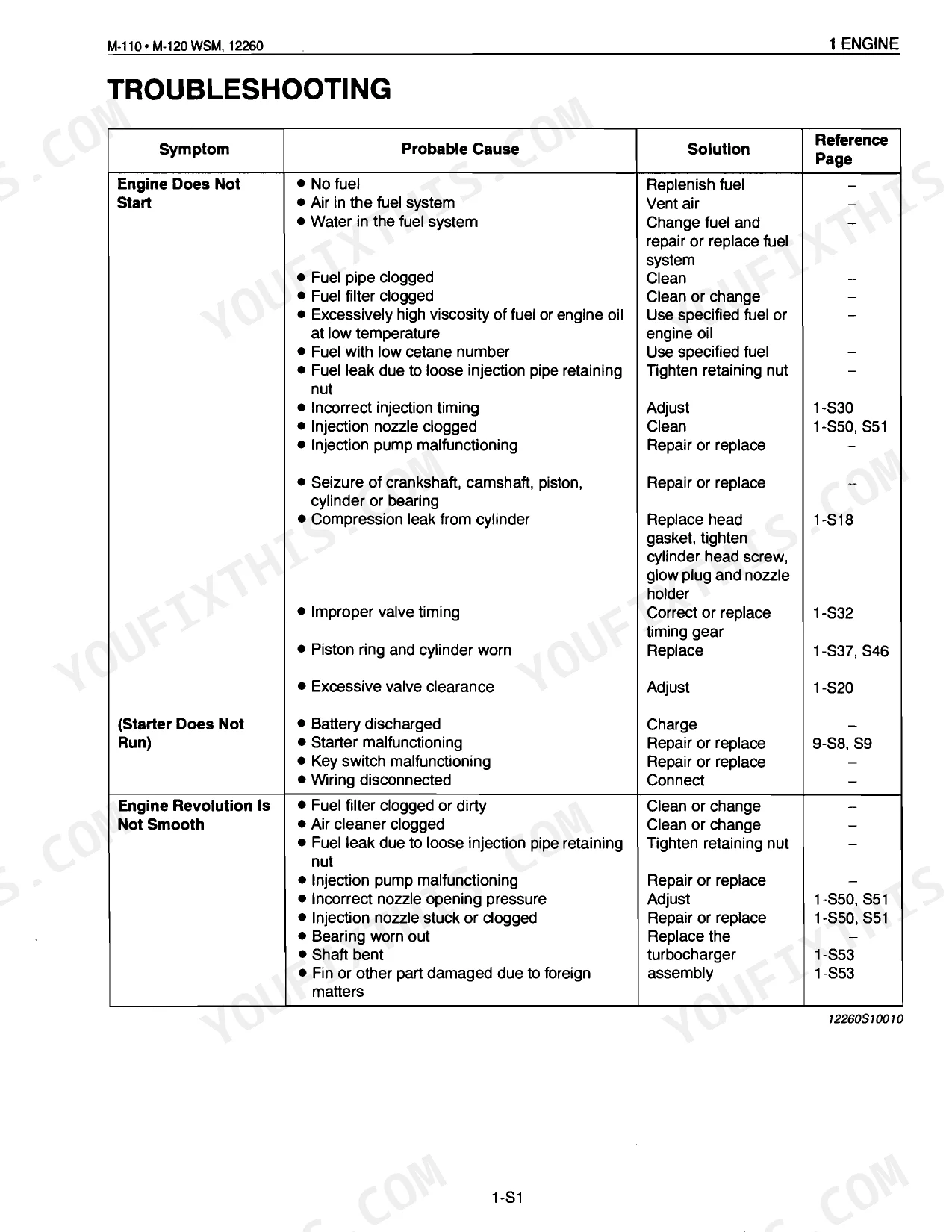
Manual Section: Transmission Power Shift System Troubleshooting (Fail-Safe)Engine does not start, revolution is not smooth, or excessive exhaust gas is observed.
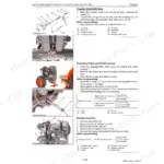
Measure cylinder compression when the engine won't start. With a gauge connected, confirm it meets the 3.6 MPa factory spec listed on page 115. If it reads low, pull the cylinder head and check surface flatness against the 0.05 mm / 100 mm limit.
Manual Section: Engine Troubleshooting p. 115Frequently Asked Questions
How do I prime the fuel system on a Kubota M-110 or M-120?
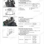
Start by filling the tank. Loosen the priming pump knob (3) and work it up and down until you feel resistance, then tighten it. Set the hand throttle to maximum and turn the key to start, then drop the throttle back to mid-speed (around 1500 min-1 (rpm)) and rev the engine to clear any remaining air. p. 50
Why is my Kubota M-120 3-point lift flashing a fast dash light and not working?
A fast blink (roughly 5 times per second) points to a fault in one of several parts: the hydraulic control lever sensor, the lift arm sensor, the lift arm top limit adjustment dial, the 3-point hitch lowering speed adjustment dial, the quick raise/lower switch, or the hitch control unit itself. It also means the fail-safe function has tripped. p. 450
What causes fuel starvation or hard starting on a Kubota M-110/M-120?
Several things can starve the engine or make it hard to start: an empty tank, air or water in the fuel, clogged fuel pipes or filter, fuel or engine oil too thick in the cold, low-cetane fuel, or a leak from a loose injection pipe retaining nut. Timing that's off, a clogged injection nozzle, or a failing injection pump round out the list. p. 110
How do I bleed air from the fuel system on a Kubota M series tractor?
Fill the tank first. Crack the priming pump knob (3) and stroke it up and down until you feel a little pressure build, then close it. With the hand throttle at maximum, start the engine and bring the throttle back to mid-speed (around 1500 min-1 (rpm)). A few seconds of revving pushes out whatever air is left. p. 50
What format is this manual in?
Download the complete 634-page searchable Service Manual right away. It opens on any device, whether that's the laptop at your desk or your phone out in the field.
Are there any print restrictions on this manual?
None. The PDF carries no DRM, so you can print any page or section you need for the shop on any standard printer.
Can I find hydraulic circuit diagrams in this Kubota M-110, M-120 manual?
It does. The manual includes hydraulic system diagrams, circuit schematics, and component specifications.


Reviews
There are no reviews yet.