
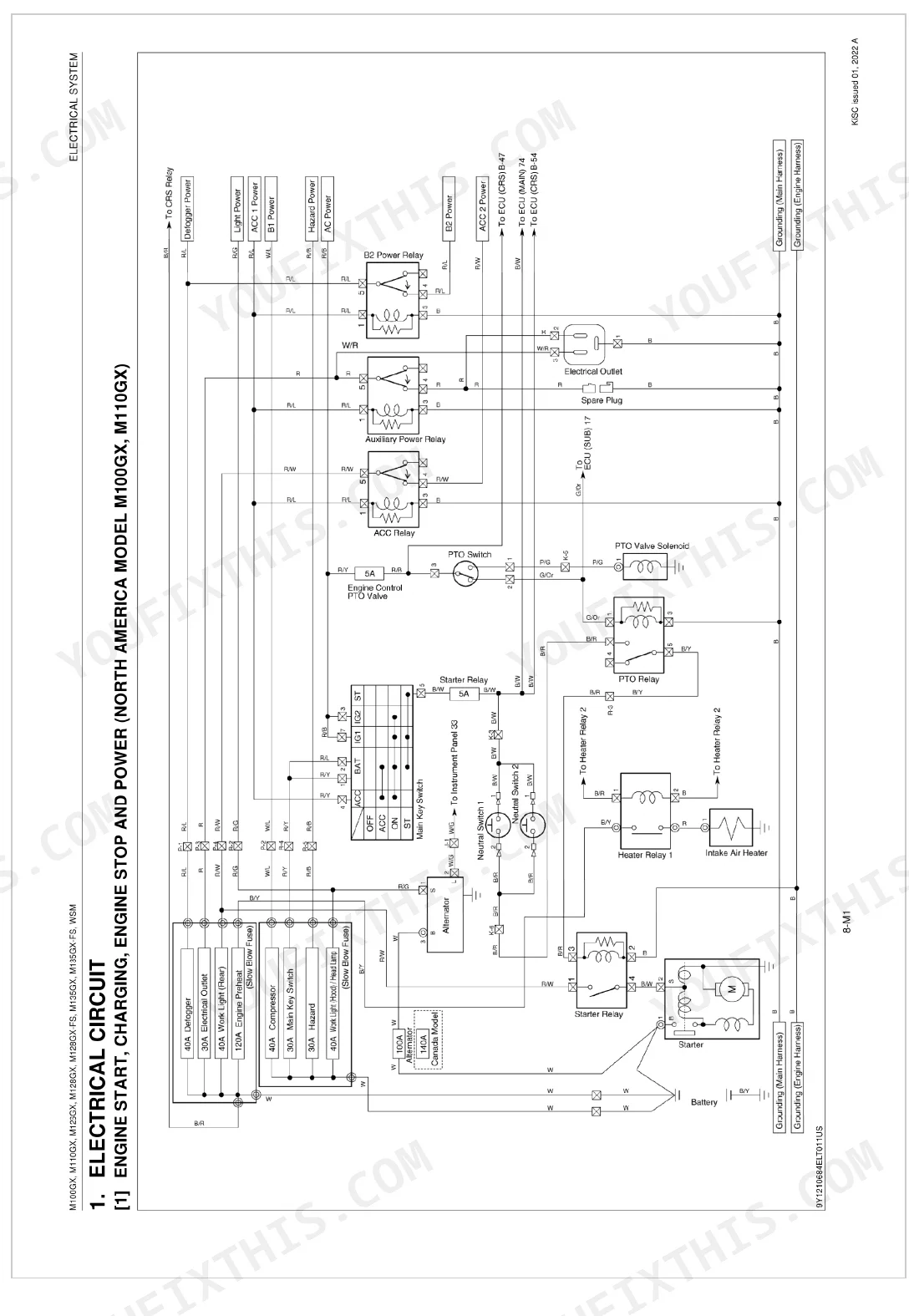
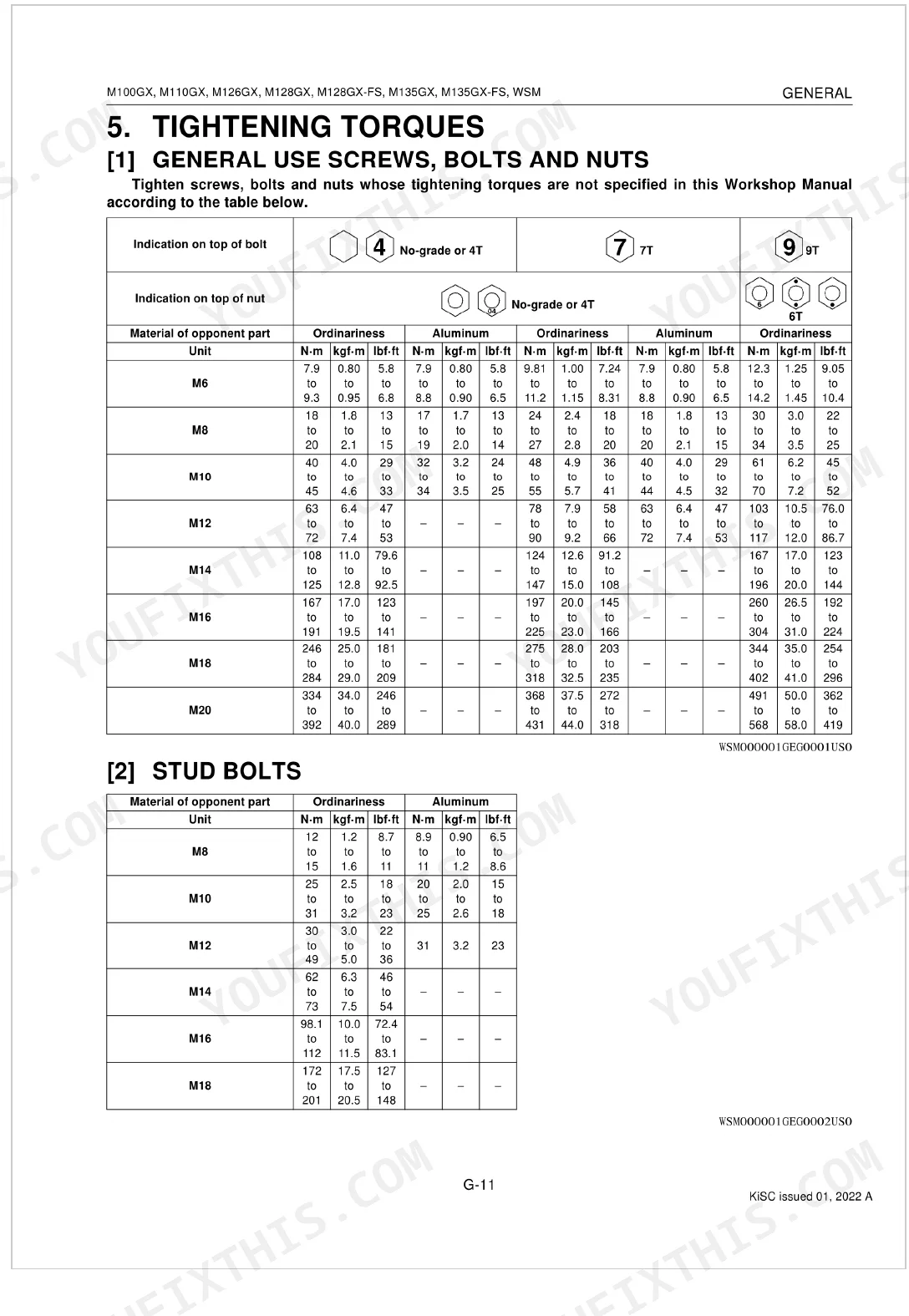


One job drives all 1,134 pages of this Kubota M100GX Workshop Manual (OEM #9Y111-20443): factory-level service across the GX line, from the M100GX up through the M135GX-FS, over the full 2001-2026 production run. The hydraulic section maps the circuit from the auxiliary control valve to the 3-point hitch through full schematics. Wiring diagrams trace the machine's individual electrical harnesses end to end. The electrical chapters lay out CAN communication circuits, Power Shift control, ECU pinouts, relay box layouts, and error codes. Torque your rear wheel mounting nuts to 343.2-402.1 N-m, a figure that lives in the torque tables rather than on a forum. When the machine is down and every hour bleeds cash, pull the PDF up on a tablet, search by keyword, and fix it right the first time.
What's Inside This Kubota M100–M135 Series Manual
| System | Pages | Key Topics |
|---|---|---|
| Information | 2-37 | Record of Revisions, Safety First, Safety Decals, Specifications, Traveling Speeds, Dimensions |
| General | 38-218 | Tractor Identification, Handling Precautions for Electrical Parts and Wiring, Lubricants, Fuel and Coolant, Tightening Torques, Maintenance for North America, Oceania |
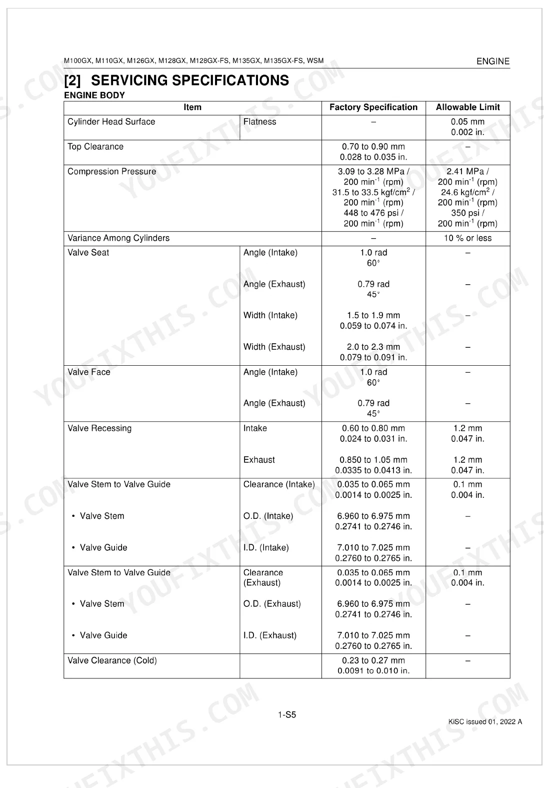
| Engine | 219-422 | Feature, Engine Body, Lubricating System, Cooling System, Intake and Exhaust System, Common Rail System |
| Transmission | 423-545 | Structure, Power Train, Power Shift System, Clutch Safety Valve, Regulator Valve, Power Shift Valve |
| Rear Axle | 546-558 | Structure (M100Gx, M110Gx, M126Gx, M128Gx, M135Gx), Servicing, Troubleshooting |
| Brakes | 559-583 | Traveling Brake, Trailer Brake, Hydraulic Trailer Brake Valve (Structure, Master Cylinder Assembly, Operation) |
| Front Axle | 584-690 | Structure (Standard Type, M100Gx, M110Gx, M126Gx, M128Gx, M135Gx), Front Suspension Type (Axle), Front Suspension System (Out Line of Front Suspension, Front Suspension Control) |
| Steering | 691-706 | Steering Mechanism, Steering Controller, Steering Cylinder, Power Steering, Power Steering Relief Valve Setting Pressure, Removing Steering Controller, Floor Mat and Panel Under Cover, Steering Post Assembly |
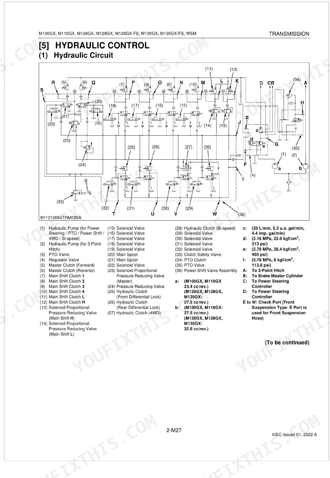
| Hydraulic System | 707-789 | Hydraulic Circuit, Structure, Outline of Hydraulic System, Auxiliary Control Valve, 3-Point Hitch System |
| Electrical System | 790-1032 | Electrical Circuit, Connectors, Location of Electric Components, Relay Box and Fuse Box, Power Shift Control System |
| Cabin | 1033-1134 | Air Conditioning System, Air Suspension Seat System, Compressor, Compressor Oil, Air Conditioner Unit, A/C Blower, System Control, Air Flow |
Quick Reference Specifications
| Specification | Value | Page |
|---|---|---|
| All Models | ||
| Rear wheel mounting nut torque | 343.2 to 402.1 N-m (35.00 to 41.00 kgf-m, 253.2 to 296.5 lbf-ft) | p. 51 |
| Cabin mount support bolt torque | 196 to 225 N-m (20.0 to 22.9 kgf-m, 145 to 165 lbf-ft) | p. 51 |
| Cabin mounting bolt torque | 196 to 225 N-m (20.0 to 22.9 kgf-m, 145 to 165 lbf-ft) | p. 51 |
| Brake hose torque | 16 to 24 N-m (1.7 to 2.4 kgf-m, 12 to 17 lbf-ft) | p. 51 |
| Trailer brake pilot pipe retaining nut (brake case side) torque | 16 to 24 N-m (1.7 to 2.4 kgf-m, 12 to 17 lbf-ft) | p. 51 |
| Brake hose adaptor torque | 16 to 24 N-m (1.7 to 2.4 kgf-m, 12 to 17 lbf-ft) | p. 51 |
| Planetary gear support mounting UBS screw torque | 90.0 to 104.0 N-m (9.18 to 10.6 kgf-m, 66.4 to 76.7 lbf-ft) | p. 51 |
| Rear axle staking nut torque | 392 to 588 N-m (40.0 to 59.9 kgf-m, 290 to 433 lbf-ft) | p. 51 |
| M100GX, M110GX | ||
| Fuel capacity | 190 L (50.2 U.S.gals, 41.8 Imp.gals) | p. 49 |
| Cooling system capacity | 9.6 L (10.1 U.S.qts, 8.5 Imp.qts) | p. 49 |
| M126GX, M128GX, M135GX | ||
| Fuel capacity | 190 L (50.2 U.S.gals, 41.8 Imp.gals) | p. 49 |
| Cooling system capacity | 14.6 L (15.4 U.S.qts, 12.8 Imp.qts) | p. 49 |
Kubota M100–M135 Series Common Problems This Manual Covers
Kubota M100GX engine oil pressure warning light stays on at idle and engine knocks.
Inspect the oil pump and relief valve first, then read the engine oil pressure at idle. A gauge reading well below the engine oil pressure spec means the pump assembly is done, so swap it. Changing the oil and filter every 200 Hr keeps sludge from building up inside.
Manual Section: Engine Troubleshooting (General)Tractor travels too far before stopping and brake pedal feels extremely spongy.
Measure the brake pedal free travel on tractors without the trailer brake model against the figures on page 571. Adjust the linkage rods until free travel sits at exactly 3.0 to 7.0 mm. From there, check the master cylinder for leaks and bleed the lines.
Manual Section: Brakes p. 571Transmission slips out of gear under heavy load and hydraulic functions stop working.
Check the fluid level at the rear dipstick. Drain the transmission case and refill to the capacity listed in the manual's Lubricants, Fuel and Coolant table. On the M135GX-FS and the rest of the GX line, swapping transmission fluid at the manual's recommended interval keeps the clutch pack friction and operating pressure where they belong.
Manual Section: GeneralCoolant temperature gauge reads completely cold or spikes erratically during field operation.
Test the sensor resistance with a multimeter, then remove the faulty unit and install a new one. Torque the coolant temperature sensor to 16 to 23 N-m, the figure given on page 301. Inspect the harness connector for corrosion and clear any stored fault codes.
Manual Section: Engine p. 301Frequently Asked Questions
What are the recommended service intervals?
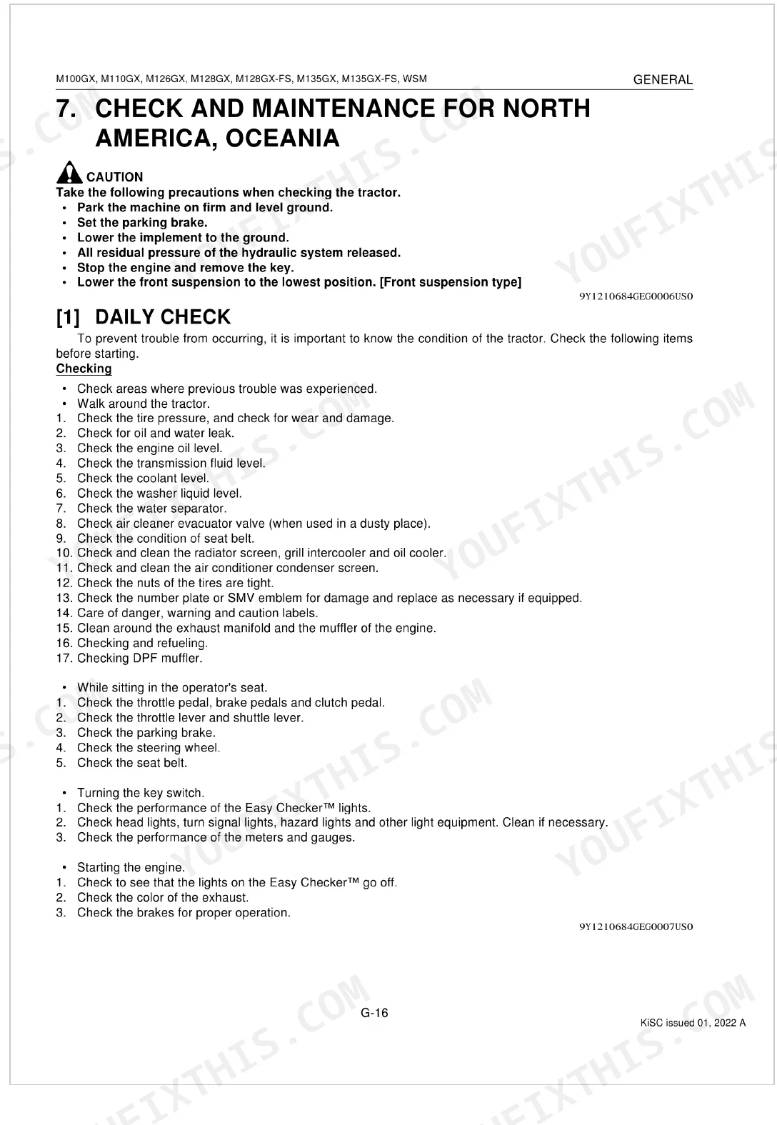
Intervals vary by component. On North America and Oceania models, check the "Engine start system" every 50 hours and replace the "Fuel filter" every 400 hours (M126GX/M135GX). The "Air cleaner element" (primary element) needs cleaning every 200 hours. p. 53
What fluids and capacities does this machine require?
Fluids and capacities split by model. On the M100GX/M110GX, the fuel tank holds 190 L, the cooling system 9.6 L, and the engine crankcase (with filter) 10.5 L. On the M126GX/M128GX/M135GX, fuel stays at 190 L, while the cooling system and crankcase (with filter) each take 14.6 L. p. 49
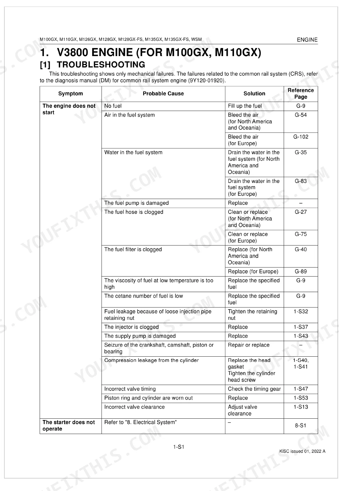
How to troubleshoot engine won't start?
When the engine won't start, a few causes are worth checking. Look for "No fuel" (fill the tank, page G-9) or "Air in the fuel system" (bleed it, page G-54). Other suspects: a malfunctioning fuel pump, a clogged pre-fuel filter (replace, page G-39), or a stuck or clogged injector (replace, page 1-S113). p. 342
What are the hydraulic system specifications?
Two numbers anchor the hydraulic system: pump delivery and relief valve setting. On the M100GX/M110GX, the pump delivers 59.7 L/min at no pressure and 57.1 L/min at rated pressure. The relief valve setting for the M100GX/M110GX runs 19.12 to 19.61 MPa (195 to 199.9 kgf/cm², 2774 to 2844 psi). p. 763
What format is this Kubota M100–M135 Series manual in?
Checkout delivers a 1134-page searchable PDF, downloadable on the spot. Open it on a laptop, tablet, or phone and carry it straight to the shop floor.
Are there any print restrictions on this Kubota M100–M135 Series manual?
Yes. Print as many copies as you like, with no restrictions. Plenty of mechanics print just the section they need and take it to the bench.
Does this Kubota M100–M135 Series Workshop Manual have electrical diagrams?
Yes. You'll find full electrical schematics with wire routing diagrams, connector identification, and circuit descriptions.


Reviews
There are no reviews yet.