




This is the Kubota service manual covering the M100X, M110X, M126X, and M135X tractors, powered by the V3800DICR-TIE3 and V6108-TIE3 diesel engines. Its 690 pages are organized into Information, General, and full mechanism and servicing coverage for every major system on these machines.
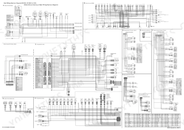
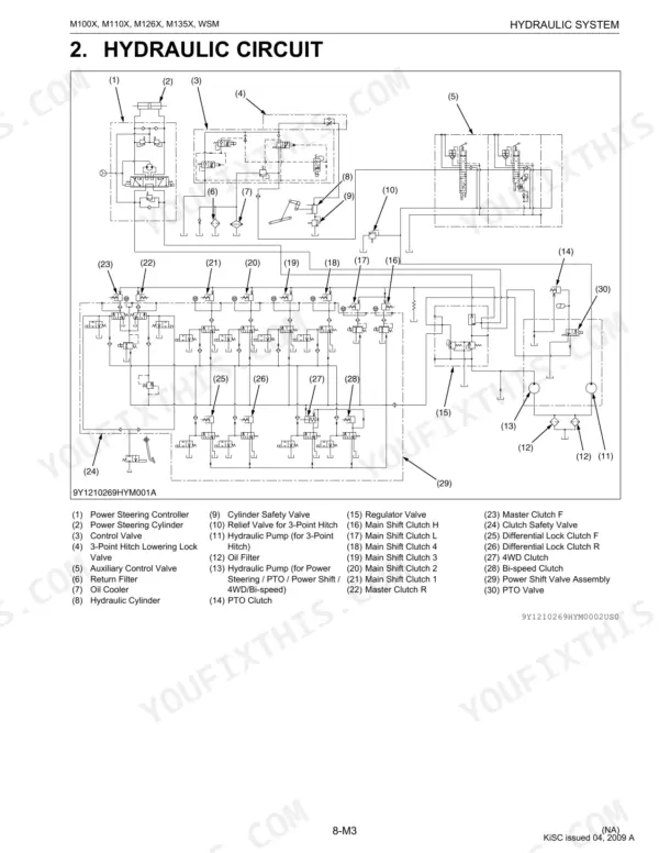
Sections run from the engine, common rail fuel system, and EGR through the clutch, power shift transmission, rear and front axles, brakes, and steering. The hydraulic system and 3 point hitch control get their own detailed treatment, and the electrical section includes wiring, the digital LCD monitor, and starting system.
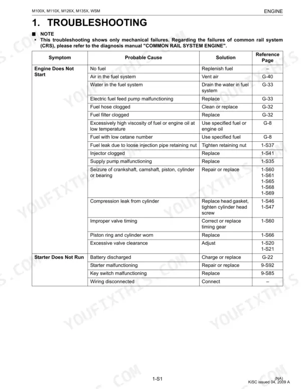
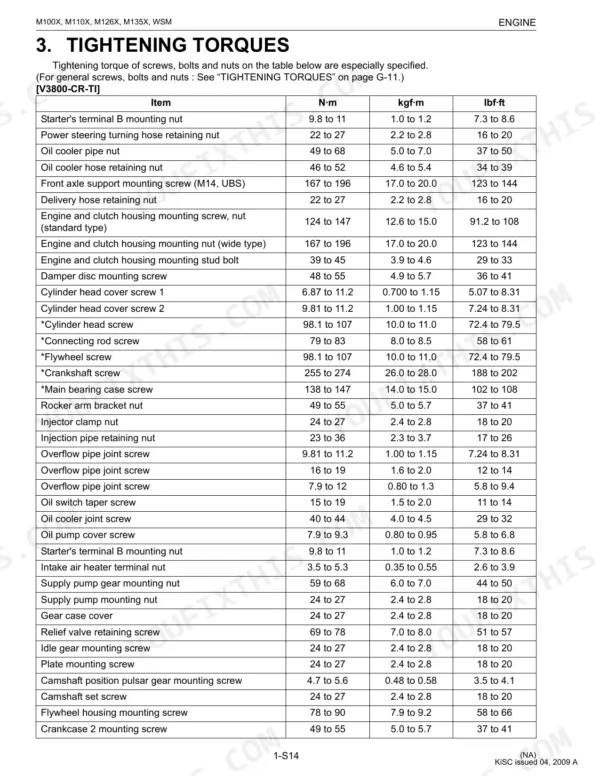
Use it to diagnose a tractor that bogs under load, chase down ECU and fuel faults, set wheel and axle torque correctly, service the master clutch, or bleed and adjust the brakes. It is an instant PDF download, readable on any device and printable page by page for shop use.
What's Inside This Manual
| System | Pages | Key Topics |
|---|---|---|
| I Information | 3-17 | |
| G General | 18-99 | Tractor Identification, Electrical Parts, Wiring, Lubricants, Fuel, Coolant, Screws, Bolts |
| Engine | 100-232 | Engine Body, Lubricating System, Cooling System, Intake and Exhaust System, Common Rail System (Crs), Exhaust Gas Recirculation (EGR) System |
| Clutch | 233-270 | Traveling Clutch, Master Clutch (Forward and Reverse), Clutch Safety Valve, Master Clutch Protection Control, PTO Clutch, Damper Disc |
| Transmission | 271-337 | Structure, Power Shift System, Hydraulic Control System, Clutch Housing Case, Differential Gear, Rear Drive Shaft |
| Rear Axle | 338-349 | Structure, Planetary Gear Support, Planetary Gear, Rear Axle Nut, Backlash Between Internal Gear and Planetary Gear |
| Brakes | 350-366 | Structure, Adjusting Brake Pedal, Brake Oil, Air Bleeding, Master Cylinder and Equalizer, Brake Case |
| Front Axle | 367-400 | Structure, Adjusting Toe-In, Adjusting Front Axle Pivot, Adjusting King-Pin Pivot, Bevel Gear Case Assembly, Differential Assembly and Differential Lock Piston |
| Steering | 401-410 | Structure, Piping and Power Steering Controller, Knuckle Arm, Power Steering Cylinder Assembly, Power Steering Controller, Power Steering Cylinder |
| Hydraulic System | 411-470 | Structure, Hydraulic Circuit, PTO Clutch Valve, Regulator Valve, Power Shift Valve, 3-Point Hitch Control System |
| Electrical System | 471-627 | Electrical Circuit Detailed Chart, Power Shift Control, Digital LCD Monitor, 4. 3-Point Hitch Control, Starting System, Opc (Operator Presence Control) |
| Cabin | 628-690 | Air Conditioning System, [1] Structure, [2] System Control, [3] Electrical System |
Documents This Manual Refers To
The manufacturer cites these publications by number. We carry them:
Quick Reference Specifications
| Specification | Value | Page |
|---|---|---|
| All Models | ||
| Front tire mounting nut | 166.7 to 196.1 N·m | p. 375 |
| Rear wheel mounting nut | 343 to 401 N·m | p. 345 |
| ECU (Main) Fuse Capacity | 10 A | p. 582 |
| ECU (SUS) Fuse Capacity | 10 A | p. 582 |
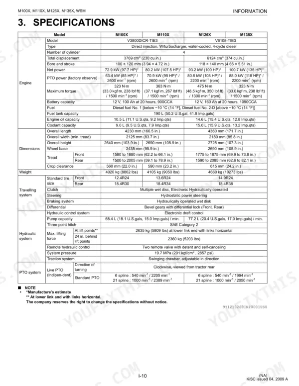
| Fuel tank capacity | 190 L | p. 27 |
| Fuel line replacement interval | every 2 years | p. 32 |
| Master Clutch Internal Snap Ring and Pressure Plate Clearance | Factory spec: 2.0 to 2.2 mm | p. 242 |
| Master Clutch Internal Snap Ring and Pressure Plate Allowable Limit | 3.6 mm | p. 242 |
| M100X, M110X | ||
| Front axle bracket mounting nut | 123.6 to 147.1 N·m | p. 375 |
| Front axle bracket mounting screw | 166.8 to 196.1 N·m | p. 375 |
| Engine Oil Capacity (M100X, M110X) | 10.5 L | p. 14 |
| M126X, M135X | ||
| Engine Oil Capacity (M126X, M135X) | 14.6 L | p. 14 |

