

Part of the Kubota Repair Manuals.
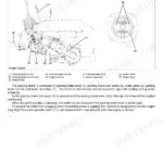
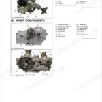
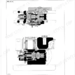
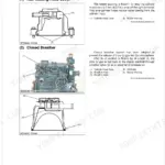
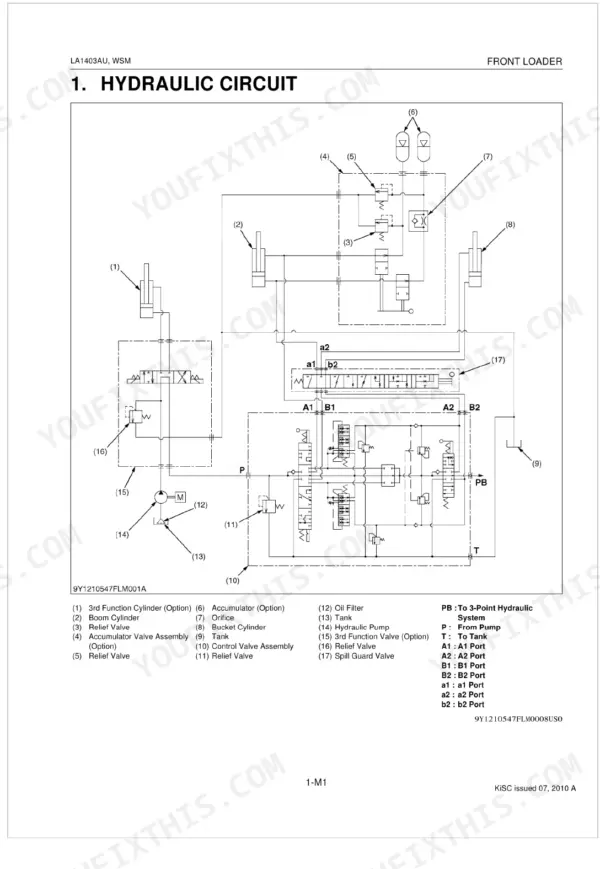
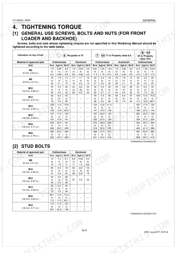
Kubota's factory document for the LA1403AU Front Loader (OEM #9Y111-05460) runs 116 pages, from hydraulic circuit diagrams through full servicing procedures. Hydraulic schematics trace the entire loader circuit, including the optional 3rd Function Valve and Hydraulic Accumulator, alongside wiring diagrams for the electrical system and exploded views. Mechanism content includes: control valve structure, Spill Guard valve operation, and boom and bucket cylinder procedures worked through in sequence. Mount the main frame with M20 screws torqued to 368 N·m; hydraulic tube connections land at 44 to 50 N·m. Wrong torque on a loader mount costs more than time. Everything is bookmarked and keyword-searchable, so you can pull it up on a tablet at the machine and get back to work.
What's Inside This Manual
| System | Pages | Key Topics |
|---|---|---|
| Information | 3-13 | |
| General | 14-23 | Loader Identification, Lubricants, Tightening Torque (Stud Bolts, American Standard Screws, Bolts and Nuts with Unc or Unf Threads, Plugs, Hydraulic Fittings) |
| Hydraulic Circuit | 26 | 3rd Function Cylinder, Boom Cylinder, Relief Valve, Accumulator Valve Assembly, Accumulator, Orifice, Bucket Cylinder, Control Valve Assembly |
| Control Valve Assembly | 27-65 | Hydraulic Circuit, Operation |
| Spill Guard System | 66-75 | Spill Guard Link, Spill Guard Valve, Spill Guard Valve Operation |
| Boom Cylinder and Bucket Cylinder | 76 | Boom Cylinder, Bucket Cylinder, Cylinder Tube, Piston Rod, Piston, Head, Nut |
| 3rd Function Valve (Option) | 77-83 | Hydraulic Circuit, 3rd Function Solenoid Valve Operation, Relief Valve (3rd Function Valve), Electrical Circuit |
| Hydraulic Accumulator (Option) | 84-87 | Hydraulic Circuit, Accumulator Valve, Hydraulic Accumulator, Accumulator Relief Valve |
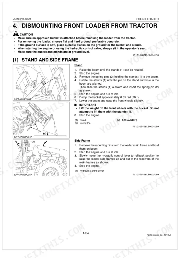
| Servicing | 88-116 | Dismounting Front Loader From Tractor, Stand and Side Frame, Hydraulic Hose |
Quick Reference Specifications
| Specification | Value | Page |
|---|---|---|
| Main frame mounting screw (M20) torque | 368 N·m | p. 91 |
| Main frame mounting screw (M18) torque | 319 N·m | p. 91 |
| Troubleshooting for Insufficient Boom Speed - Oil leaks from tube joints | Repair | p. 89 |
| Hydraulic tube and hose torque | 44 to 50 N·m | p. 91 |
| Hydraulic fittings (Tapered screw R1/8) torque | 13 to 21 N·m | p. 19 |
| Adjustable elbow, Adaptor (O-ring port) (UNF) 9/16 torque | 37 to 44 N·m | p. 20 |
| Control valve mounting bolt (M10) torque | 48 to 55 N·m | p. 91 |
| Relief valve setting pressure for control valve | 20.2 to 20.7 MPa | p. 96 |
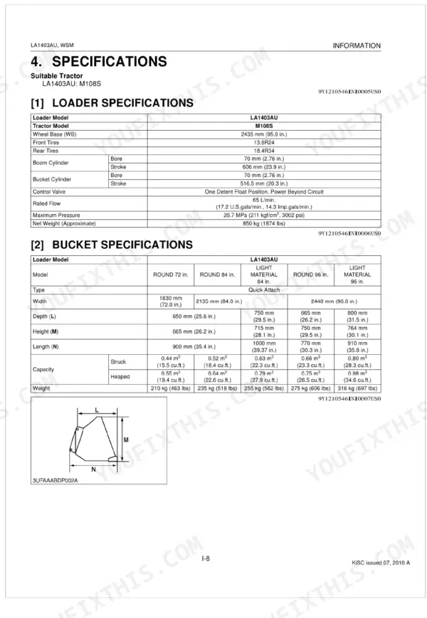
| Rated Flow | 65 L/min. | p. 12 |
| Maximum Pressure (Hydraulic) | 20.7 MPa | p. 12 |
| Raising Time (Boom) | 5.2 sec. | p. 13 |
| Transmission Case Capacity | 60.0 L | p. 18 |