


Part of the Kubota Parts Manuals.
Looking up a seal kit for your Kubota LA272 loader? This 32-page parts catalog breaks the tractor down to individual fasteners across exploded-view sections, from main frame hardware to full hydraulic hose routing. Separate parts lists cover both the 3-position and 4-position control valve kits, alongside component breakdowns for the boom and bucket cylinders. Each cylinder section splits out tube, rod, head, piston, and Kit Seal as individual line items, so you order only what failed instead of the whole assembly. The control valve sections run just as deep: Cap-Spool, Kit Detent Float, Assy Relief Valve, and Kit Load Check all carry their own reference numbers. No more squinting at part numbers on a blurry dealer fax. Bookmarked by assembly and searchable by keyword, you can jump to the boom section, confirm a number, and place the order without leaving your screen.
What's Inside This Kubota LA272 Parts Manual
| System | Pages | Key Topics |
|---|---|---|
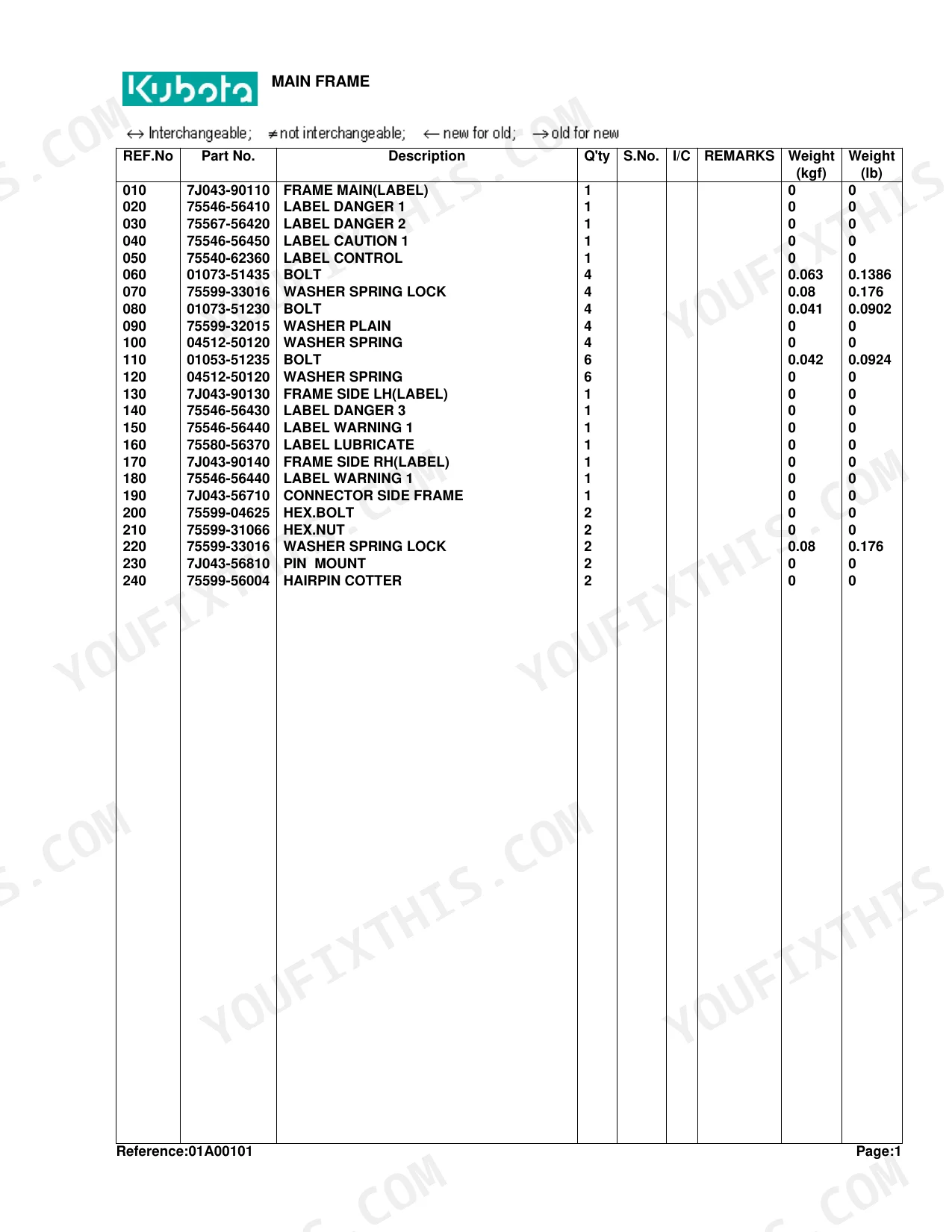
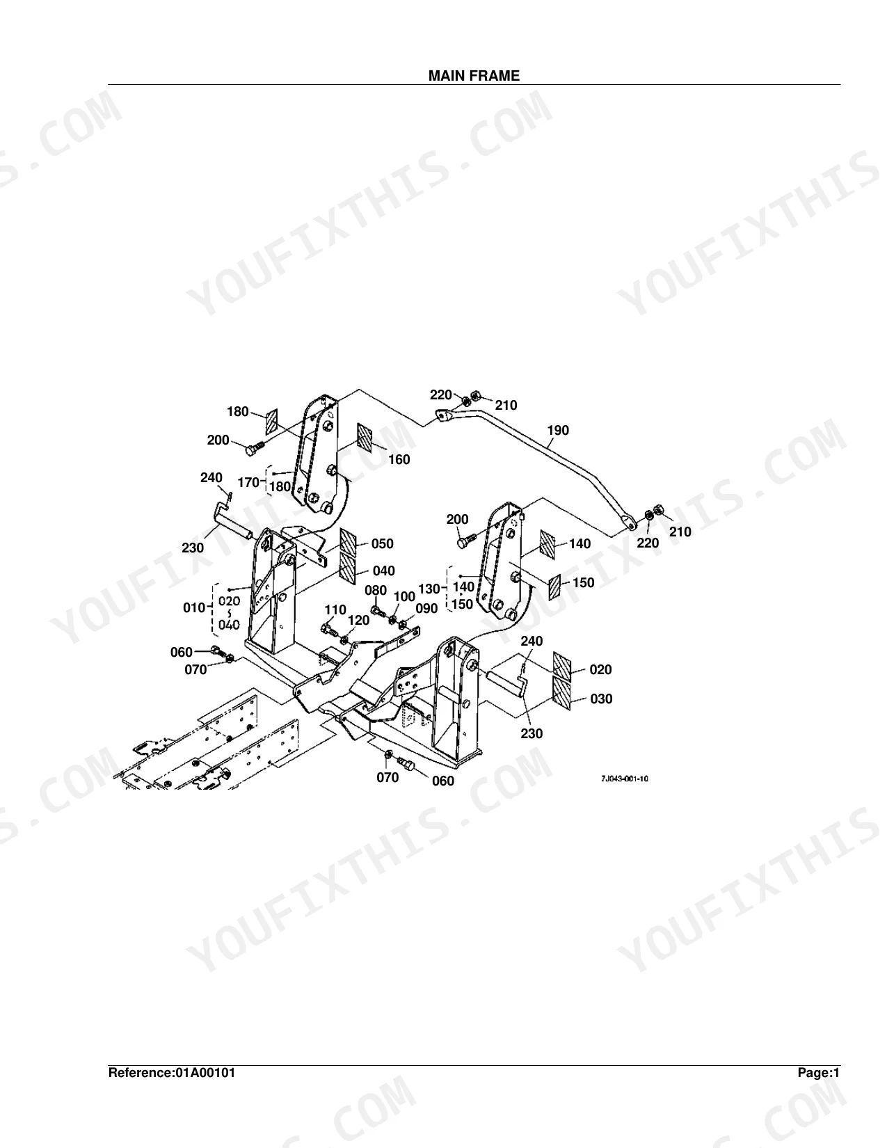
| Main Frame | 4-5 | Frame Main, Bolt, Washer Spring Lock, Hex.Bolt, Hex.Nut, Pin Mount |
| Cylinder/Hydraulic Hose | 6-7 | Cylinder, Hydraulic Hose, Band Code |
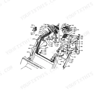
| Hydraulic Tube | 8-9 | Clamp, Hex.Bolt, Washer Spring |
| Hydraulic Hose 1 | 10-11 | Hydraulic Hose, Coupler, Plug Dust, Sleeve, Band Code |
| Hydraulic Hose 2 | 12-13 | Adapter, Band Code, Block Hydraulic, O-Ring, Hydraulic Hose |
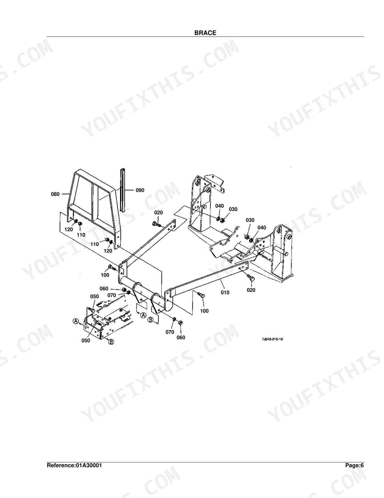
| Brace | 14-15 | Hex.Bolt, Hex.Nut, Washer Spring Lock |
| Boom | 16-17 | Cotter, Fitting Grease, Pin, Bucket, Edge Cutting |
| Control Valve [3-Position Valve Kit] | 18-19 | Stay Valve, Valve Control, Adapter, O-Ring, Elbow, Nipple |
| Control Valve [4-Position Valve Kit] | 20-21 | Stay Valve, Hex.Bolt, Washer Spring Lock, Valve Control, Assy Adapter, O-Ring |
| Control Valve [Component Parts] [3-Posi.Valve Kit] | 22-23 | Valve Control, Cap-Spool, Kit Detent Float, Assy Relief Valve, Cap Screw-Soc.Hd., Kit Load Check |
| Control Valve [Component Parts] [4-Posi.Valve Kit] | 24-25 | Valve Control, Cap-Spool, Kit Detent Float, Kit Detent Regen., Assy Relief Valve, Cap Screw-Soc.Hd. |
| Control Lever [3,4-Position Valve Kit] | 26-27 | Lever, Bushing, Rod, Pin, Washer Plain, Pin Cotter |
| Cylinder (Boom) [Component Parts] | 28-29 | Tube, Rod, Head, Piston, Kit Seal |
| Cylinder (Bucket) [Component Parts] | 30-31 | Tube, Rod, Head, Piston, Kit Seal (Bucket) |
| Accessories and Service Parts | 32 | - |
Quick Reference Specifications
| Specification | Value | Page |
|---|---|---|
| BOLT (REF.No 060) Quantity | 4 | p. 5 |
| BOLT (REF.No 060) Weight | 0.063 kgf | p. 5 |
| WASHER SPRING LOCK (REF.No 070) Quantity | 4 | p. 5 |
| WASHER SPRING LOCK (REF.No 070) Weight | 0.08 kgf | p. 5 |
| BOLT (REF.No 110) Quantity | 6 | p. 5 |
| BOLT (REF.No 110) Weight | 0.042 kgf | p. 5 |
| WASHER SPRING LOCK (REF.No 220) Quantity | 2 | p. 5 |
| WASHER SPRING LOCK (REF.No 220) Weight | 0.08 kgf | p. 5 |
| WASHER SPRING LOCK (REF.No 040) Quantity | 8 | p. 15 |
| WASHER SPRING LOCK (REF.No 040) Weight | 0.08 kgf | p. 15 |
| GRIP LEVER (REF.No 120) Quantity | 1 | p. 27 |
| GRIP LEVER (REF.No 120) Weight | 0.05 kgf | p. 27 |
Kubota LA272 Common Problems This Manual Covers
Can't find the correct Kubota LA272 boom cylinder seal kit part number for a leaking rod gland.
Inspect the boom cylinder exploded view on page 28. Identify the exact kit seal part number for your serial range. Verify you have the correct 0.08 kgf spring lock washers (REF.No 070) listed on page 5 for the frame mount during reassembly.
Manual Section: Cylinder (Boom) [Component Parts] p. 28Missing joystick knob and need the exact part number to replace a worn out control lever grip.
Pull up the control lever diagram on page 26. Locate the lever grip (REF.No 120), weighing 0.05 kgf, on page 27. Match this number against your 3-position or 4-position valve kit configuration before ordering.
Manual Section: Control Lever [3,4-Position Valve Kit] p. 26Need replacement mounting hardware part numbers after breaking bolts on the loader brace assembly.
Check the brace parts diagram on page 14. Find the hex bolts and the 8 spring lock washers (REF.No 040), 0.08 kgf each, on page 15. Order the exact quantities listed to secure the boom attachments.
Manual Section: Brace p. 14Blown hydraulic hose on the main frame and need the correct replacement hose part number.
Examine the cylinder and hydraulic hose diagram on page 6. Match your hose configuration using the band codes provided. Look up the 6 mounting bolts (REF.No 110), 0.042 kgf each, on page 5 to replace any stretched frame hardware.
Manual Section: Cylinder/Hydraulic Hose p. 6Frequently Asked Questions
How quickly can I access this manual after buying?
Immediate download of the complete 32-page searchable Parts Catalog. Open it on any device, from the laptop at your desk to the phone in the field.
Can I print this manual?
No restrictions at all. Print individual pages, full chapters, or the entire manual. The PDF is completely unlocked.
Where do I find the boom cylinder seal kit part number for the Kubota LA272?
The boom cylinder exploded view is on page 28. Locate the Kit Seal line item for your serial range there. For frame mount reassembly, page 5 lists the required 0.08 kgf spring lock washers (REF.No 070).
What is the part number for the Kubota LA272 control lever grip?
The control lever grip (REF.No 120), weighing 0.05 kgf, is listed on page 27. The control lever diagram on page 26 shows the full assembly. Confirm whether your loader uses the 3-position or 4-position valve kit before ordering.
What hardware do I need to replace broken mounting bolts on the LA272 brace assembly?
Page 14 shows the brace parts diagram. The required spring lock washers (REF.No 040) are listed on page 15 at 0.08 kgf each, with 8 needed to secure the boom attachments. Order the exact quantities shown.
How do I identify the correct hydraulic hose part number for the Kubota LA272 main frame?
The cylinder and hydraulic hose diagram is on page 6. Match your hose using the band codes provided. Page 5 also lists the 6 frame mounting bolts (REF.No 110) at 0.042 kgf each for any frame hardware replacement.


Reviews
There are no reviews yet.