


Part of the Kubota Parts Manuals.
Need the right OEM number for your front-end loader before you call the dealer? This 29-page catalog maps the LA301 and LA351 down to the part, with exploded views and numbered lists for the main frame, boom, and control valve. The valve section breaks out to component-level kits for detent float, regen, and load check, and both boom and bucket cylinders get their own internal breakdowns alongside hydraulic hoses, hydraulic tubes, and the front guard. Serial breaks are called out where they matter: the quick-coupler switches to a different part at S.No. 14168 on the LA301 and S.No. 13338 on the LA351, so the order matches the machine. Search by part name or keyword, then bookmark-jump straight to the assembly you need, whether you're at the counter or in the cab.
What's Inside This Kubota LA301, LA351 Parts Manual
| System | Pages | Key Topics |
|---|---|---|
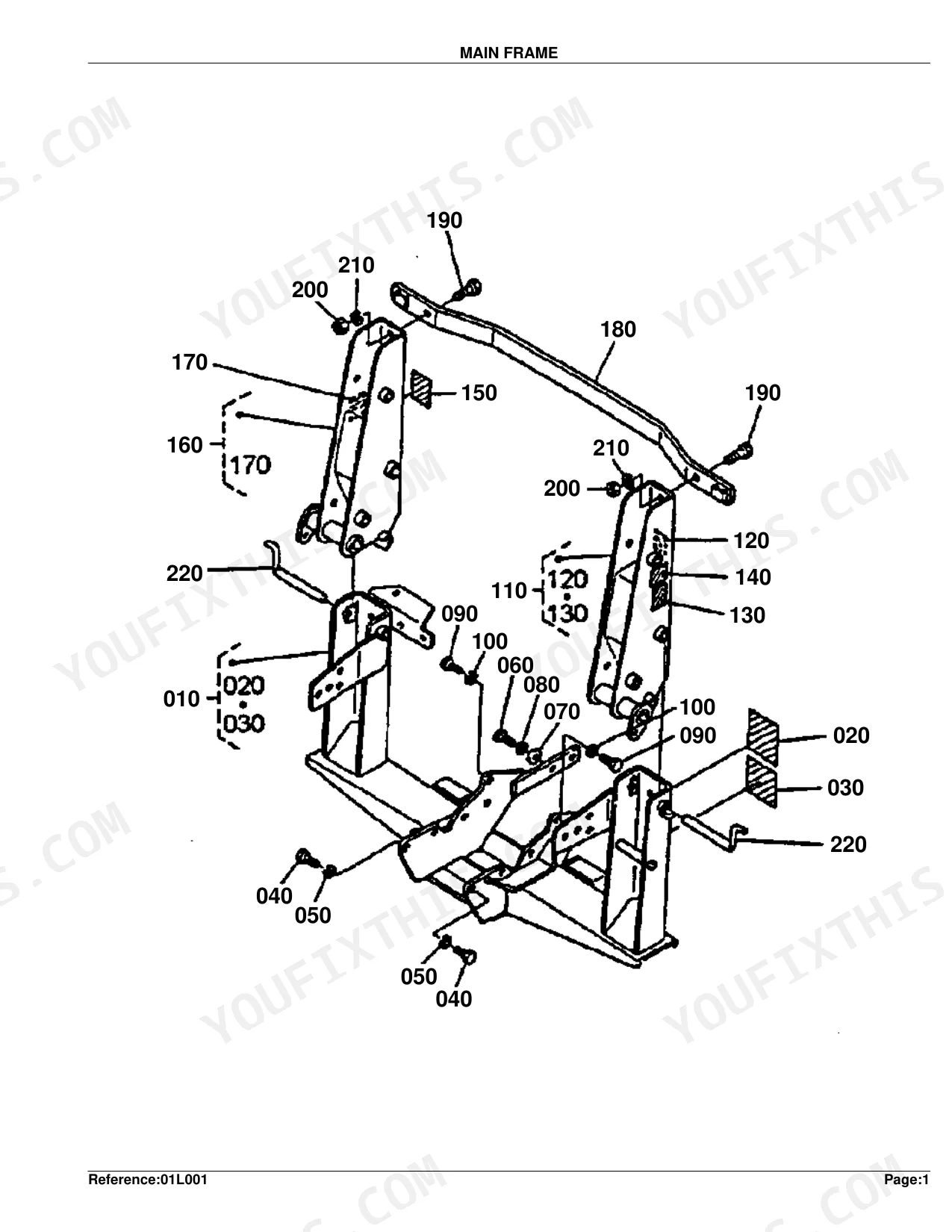
| Main Frame | 3-4 | Frame Main, Label Danger, Label Caution, Hex.bolt, Frame Side LH, Label Warning, Label Model, Label Lubricate |
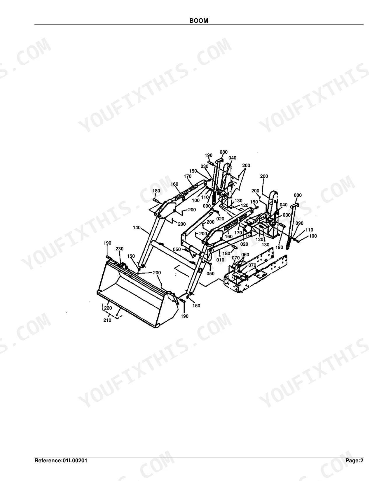
| Boom | 5-6 | Brace, Hex.bolt, Hex.nut, Stand, Collar, Fitting Grease, Label Kubota |
| Control Valve | 7-8 | Stay Valve, Hex.bolt, Hex.nut, Valve Control, Assy Adapter, Assy Elbow Adjustabl, Throttle, Nipple |
| Control Valve/Control Lever | 9-10 | Stay Valve, Hex.bolt, Hex.nut, Valve Control, Assy Adapter, Assy Elbow Adjustabl, Throttle, Assy Plug Orifice |
| Control Valve [Component Parts] | 11-14 | Valve Control, Kit Detent Float, Kit Detent Regen, Assy Relief Valve, Kit Load Check, Kit Seal, Kit Upper Boom Spool, Kit Upper Bucket Spo |
| Control Lever | 15-16 | Lever, Bushing, Collar, Rod, Joint Rod End, Hex.nut, Lever Control, Grip Lever |
| Cylinder-Hydraulic Hose | 17-18 | Cylinder, Mark White, Mark Yellow, Mark Blue, Mark Red, Assy Hose Hydrauli, Hose Hydraulic, Coupler |
| Cylinder (Boom) [Component Parts] | 19-20 | Cylinder, Tube Comp, Rod Comp, Head, Piston, Kit Seal, Fitting Grease |
| Cylinder (Bucket) [Component Parts] | 21-22 | Cylinder, Tube Comp, Rod Comp, Head, Piston, Kit Seal, Fitting Grease |
| Hydraulic Tube | 23-24 | Tube Hydraulic, Hex.bolt, Clamp, Washer |
| Hydraulic Hose | 25-26 | Hose Hydraulic, Adapter, Band Code, Block Hydraulic |
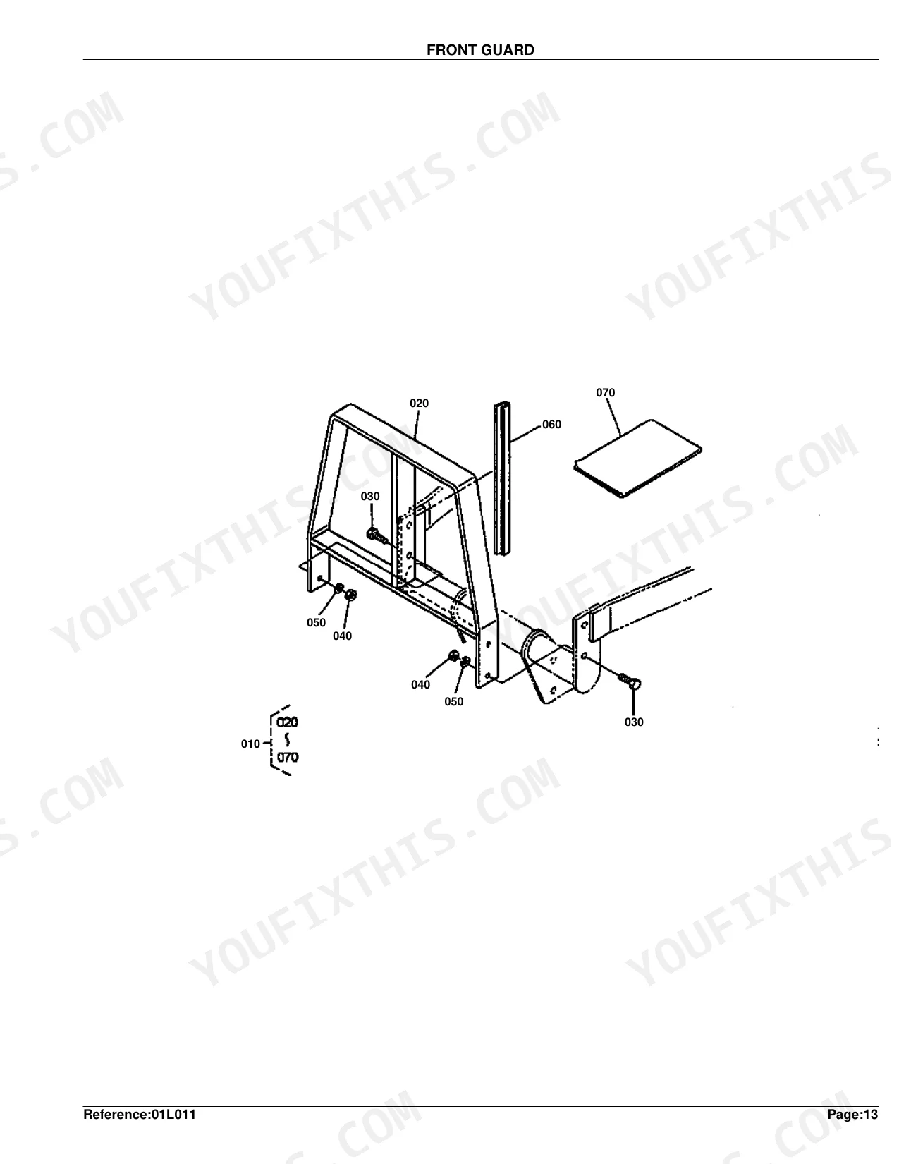
| Front Guard | 27-29 | Kit Guard Front, Hex.bolt, Hex.nut, Cushion, Manual Assembly for Option Only |
Quick Reference Specifications
| Specification | Value | Page |
|---|---|---|
| All Models | ||
| Weight of HOSE 1 HYDRAULIC (REF.No 080) | 0.25 kgf | p. 18 |
| Weight of HOSE 8 HYDRAULIC (REF.No 120) | 0.25 kgf | p. 18 |
| Weight of KIT SEAL (CYLINDER (BOOM)) (REF.No 070) | 0.002 kgf | p. 20 |
| Weight of KIT SEAL (CYLINDER (BUCKET)) (REF.No 070) | 0.002 kgf | p. 22 |
| Weight of PIN (MAIN FRAME) (REF.No 220) | 0.74 kgf | p. 4 |
| LA301 (S.No. >=14168), LA351 (S.No. >=13338) | ||
| Weight of COUPLER (REF.No 090) for S.No. >=14168 | 0.13 kgf | p. 18 |
| Weight of VALVE CONTROL (REF.No 050) | 0.008 kgf | p. 10 |
| Weight of BUSHING (CONTROL VALVE/CONTROL LEVER) (REF.No 180) | 0.01 kgf | p. 10 |
| LA301 (S.No. <=14167), LA351 (S.No. <=13337) | ||
| Weight of VALVE CONTROL (REF.No 050) | 7.3 kgf | p. 8 |
| Weight of LEVER (REF.No 010) | 0.13 kgf | p. 16 |
| Weight of LEVER CONTROL (REF.No 110) | 0.5 kgf | p. 16 |
Kubota LA301, LA351 Common Problems This Manual Covers
Kubota LA301 and LA351 boom cylinder leaking fluid down the rod under heavy load
Open the exploded view on page 20 and read the boom cylinder seal kit number straight off the callout. The full seal package lists at 0.002 kgf, so you can confirm the kit matches. Cross-check your serial number against the parts index column first, since the listings split by machine.
Manual Section: Cylinder (Boom) [Component Parts] p. 20Cracked, missing, or loose mounting hardware around the loader main frame attachment points
Compare your loose or damaged hardware against the page 4 frame diagram to pin down the hex bolts and spring lock washers you need. The main frame label assembly carries a 59 kgf (129.8 lb) weight if you want to double-check the group. Order the pin and connector side frame by the numbers shown in that breakdown.
Manual Section: Main Frame p. 4Excessive physical play, binding, or generally poor response at the joystick control lever
Review the parts breakdown on page 16 for older models with serial numbers up to 14167. Locate the correct bushings, clevis pins, and the complete control lever assembly weighing 0.5 kgf (1.1 lb). Order the exact replacement items listed in the diagram to restore tight operation.
Manual Section: Control Lever p. 16Hydraulic oil visibly dripping around the front adapter blocks and main hose connections
Follow the routing on page 26 to land on hydraulic hose 7, the one running to the front adapter blocks. At 0.6 kgf (1.32 lb), the weight figure confirms you've matched the original. Then grab the O-rings and adapter fittings called out alongside it so the job goes back together in one pass.
Manual Section: Hydraulic Hose p. 26Frequently Asked Questions
What are the replacement specifications for hydraulic hoses?
Each hydraulic line carries its own part number, so you order by the exact one. Hose 8 Hydraulic is 75532-66610, Hose 9 Hydraulic is 75536-66620, and Hose 10 Hydraulic is 75532-66630. Matching the number to the line is how you avoid fitting the wrong hose. p. 18
What are the replacement specifications for quick couplers / quick-attach connections?
Which coupler you need comes down to your serial number. On machines at S.No. 14167 or below, the coupler is 75532-66323; from S.No. 14168 up, it changes to 75536-66320. Check the number stamped on your loader before ordering so you don't cross the break. p. 18
What seal kit fits the boom cylinder on the LA301 and LA351?
Page 20 shows the boom cylinder exploded view with the seal kit (Kit Seal) listed directly in the callout. The kit weighs 0.002 kgf, which lets you confirm you have the right package when it arrives. Check the serial-number column before ordering, since part listings split by machine. p. 20
Which control lever parts are listed for the LA301 and LA351?
Page 16 covers the control lever assembly. The diagram breaks out the lever, bushing, collar, rod, joint rod end, and grip lever. On machines with serial number 14167 and below, the lever control assembly weighs 0.5 kgf (1.1 lb). Order by the part numbers shown in that diagram to restore tight movement at the joystick. p. 16
How will I receive this Kubota LA301, LA351 Parts Catalog?
It downloads as a PDF the moment your payment clears. The full 29-page searchable catalog is yours right away, ready to open on a laptop, tablet, or phone in the shop.
Are there any print restrictions on this manual?
Print as many copies as you like. Plenty of mechanics run off just the section they need and carry it out to the shop floor.


Reviews
There are no reviews yet.