
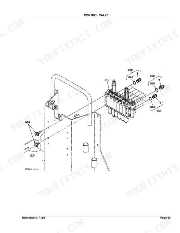
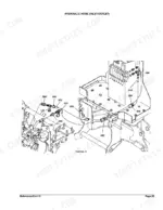
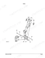
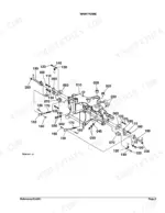
Part of the Kubota Parts Manuals.
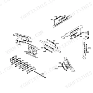
This is the Kubota parts catalog for the BT600 backhoe attachment, a 74-page PDF you download and keep. It breaks the backhoe into its assemblies: the bucket, main frame, swing frame, boom, dipperstick and stabilizer, plus every cylinder, the control valve and each hydraulic hose run, shown as exploded diagrams with Kubota part numbers.
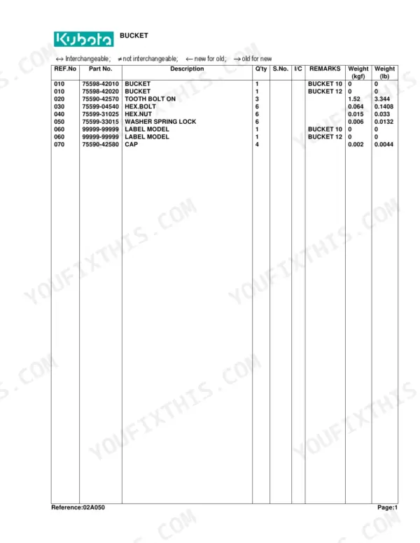
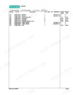
Use it to identify the exact part before you order. Match a worn cylinder, seal, spool, pin or hose to its number, and use the serial-number columns to confirm the right version for your machine.
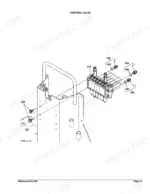
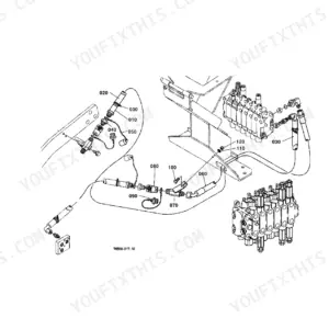
The catalog details the control valve down to individual spool sections for the bucket, dipperstick, stabilizer, boom and swing circuits, along with the inlet, swing, boom and bucket hoses, making it the reference for any BT600 hydraulic repair or parts lookup.
What's Inside This Kubota BT600 Parts Manual
| System | Pages | Key Topics |
|---|---|---|
| Hydraulics & 3-Point Hitch | Swing Cylinder, Boom Cylinder, Dipperstick Cylinder, Bucket Cylinder, Stabilizer Cylinder, Control Valve, Hydraulic Hose | |
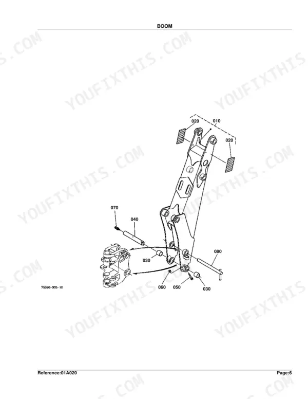
| Loader, Backhoe & Attachments | Bucket, Swing Frame, Boom, Dipperstick, Bucket Link, Stabilizer Arm | |
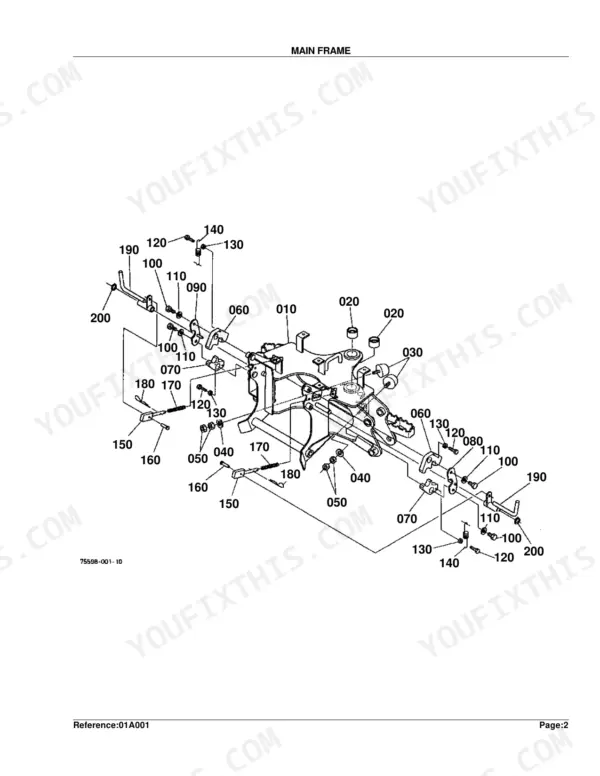
| Body & Operator Station | Main Frame, Step, Shutter Plate Kit | |
| Decals & Accessories | Label, Accessories and Service Parts | |
| Other Components | Spool Section, Control Lever 1, Control Lever 2 |
Kubota BT600 Common Problems This Manual Covers
Weak or slow boom and bucket action
Loss of digging power or sluggish boom, dipper and bucket movement often traces to internal leakage in the control valve. This section maps the valve so you can order the right seals and spools.
Manual Section: Control Valve p. 41Hydraulic drips under the backhoe
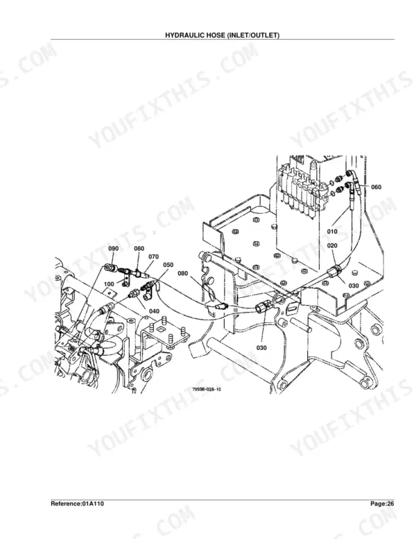
Wet hoses and puddling under the machine usually come from a leaking hose or loose fitting. The inlet and outlet hose section lists each line for an exact replacement.
Manual Section: Hydraulic Hose (Inlet/Outlet) p. 55Boom cylinder seal wear
A boom cylinder that seeps oil or will not hold load needs new seals. Use the boom cylinder component diagram to match the seal kit and internal parts by number.
Manual Section: Boom Cylinder [Component Parts] p. 19Bucket cylinder leaking or weak
Owners rebuild bucket cylinders when seals wear and the cylinder loses power. This section shows the cylinder and its component parts so you can order the correct rebuild parts.
Manual Section: Bucket Cylinder [Component Parts] p. 31Swing function loses power
A swing that is weak or drifts often means worn swing-cylinder seals. The component-parts diagram identifies the seals and internal pieces for this circuit.
Manual Section: Swing Cylinder [Component Parts] p. 13Erratic or lost proportional control
Intermittent control or lost fine metering usually points to a worn spool or internal valve wear. The control valve component section breaks the valve down for inspection.
Manual Section: Control Valve [Component Parts] p. 43Frequently Asked Questions
What machine is the Kubota BT600 backhoe for?
The BT600 is a Kubota backhoe attachment fitted to compact tractors such as the BX-series. This catalog covers the backhoe itself, its cylinders, control valve and hydraulic hoses by Kubota part number.
Does the catalog break down the control valve?
Yes. Beyond the main control valve, it details each spool section separately for the bucket, dipperstick, stabilizer, boom and swing circuits, so you can identify individual valve parts. p. 41
Can I look up the hydraulic hose parts?
Yes. The catalog covers the inlet and outlet, swing, boom and dipperstick, bucket and stabilizer hose runs, each with its own diagram and part list for ordering exact replacements. p. 55
What do I get after purchasing this Kubota BT600 manual?
You get a 74-page searchable PDF that downloads instantly after checkout. Open it on your laptop, tablet, or phone — bring it right to the shop floor.
Am I able to print pages from this manual?
Yes. Print the sections you need to take out to the shop for your own use. Standard letter or A4 paper works.
Does this Kubota BT600 manual include hydraulic diagrams or wiring information?
This is a parts catalog, not a workshop manual. It contains exploded parts diagrams with part numbers for every major assembly. It does not include wiring diagrams, hydraulic circuit drawings, or service procedures. Use it to identify and order the correct replacement parts for the Kubota BT600.


Reviews
There are no reviews yet.