
Part of the Kubota Parts Manuals.
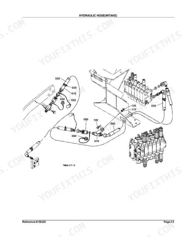
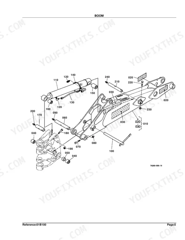
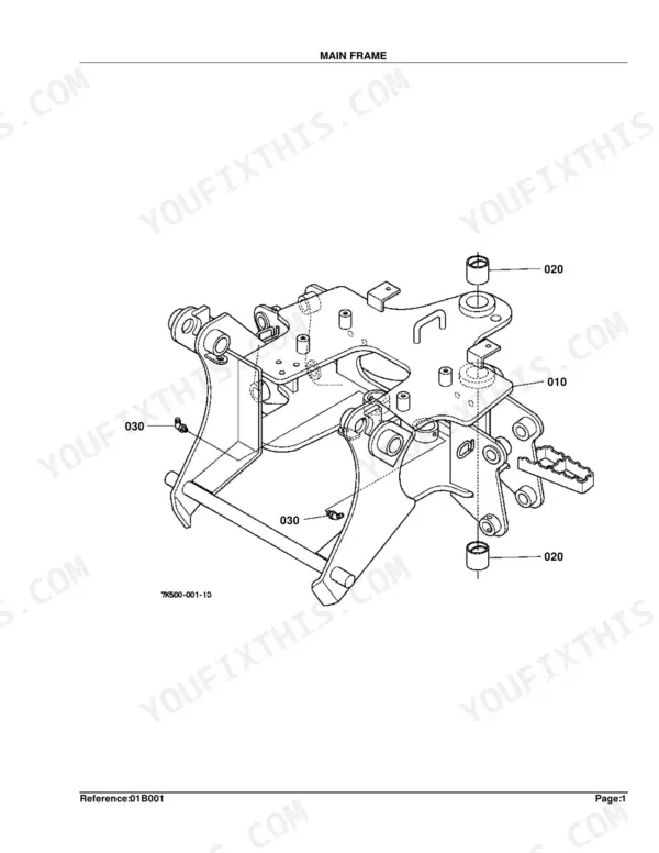
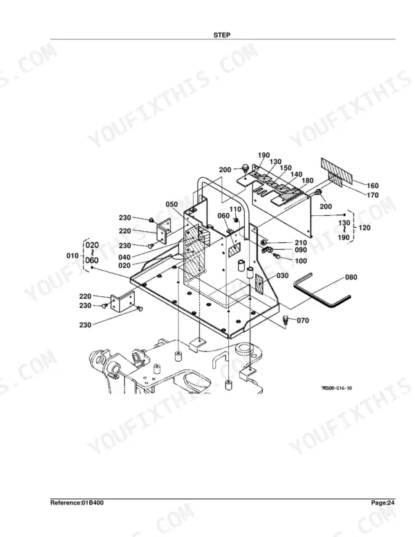
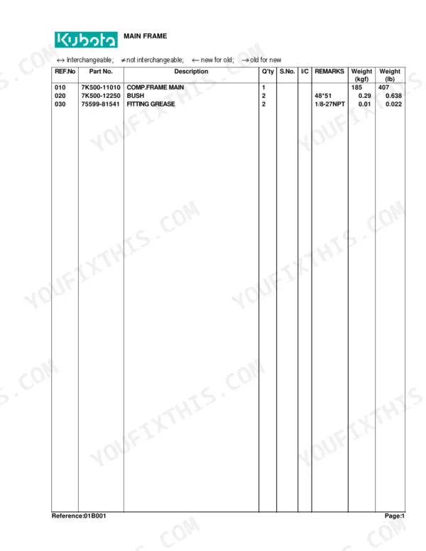
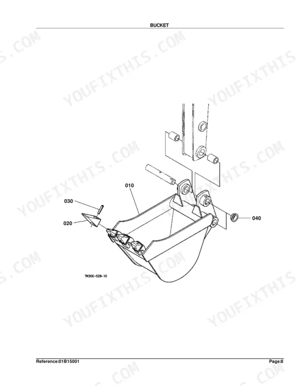
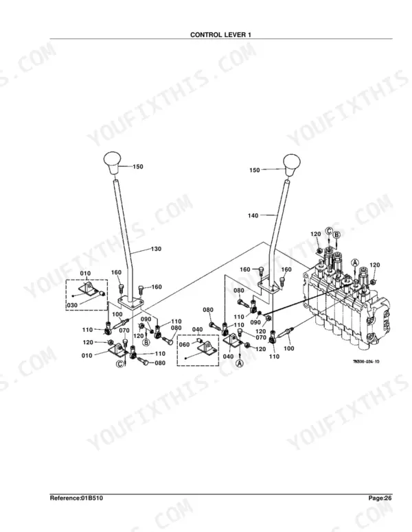
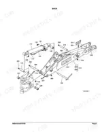
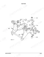
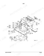
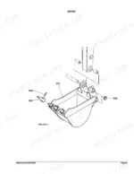
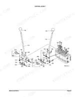
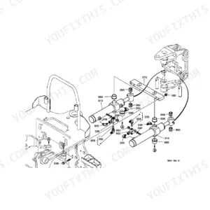
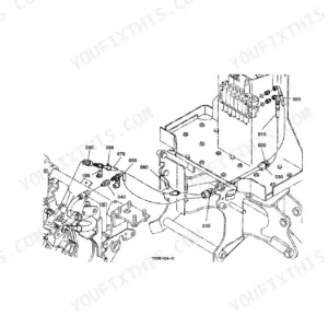
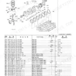
This is the Kubota parts catalog for the BH90 backhoe attachment, a 65-page PDF you download and keep. It breaks the backhoe into its assemblies: the main frame, sub frame, swing frame, boom, dipperstick, bucket and stabilizer, plus the control valve, hydraulic hoses and every cylinder, each shown as an exploded diagram with Kubota part numbers.
Use it to identify the exact part before you order. Match a worn pin, bushing, seal, cylinder or valve part to its number, and use the serial-number columns to confirm the right version for your machine.
The catalog details the control valve and its component parts, the swing, boom, dipper, bucket and stabilizer cylinders, the full set of hydraulic hoses, and the tractor mount kits, making it the reference for any BH90 repair or parts lookup.
What's Inside This Kubota BH90 Parts Manual
| System | Pages |
|---|---|
| Main Frame | |
| Sub Frame | |
| Swing Frame | |
| Swing Cylinder | |
| Boom | |
| Dipperstick | |
| Bucket Link | |
| Bucket | |
| Stabilizer Arm | |
| Control Valve | |
| Control Valve [Component Parts] | |
| Hydraulic Hose (Intake) | |
| Hydraulic Hose (Inlet/Outlet) | |
| Hydraulic Hose (Swing) | |
| Hydraulic Hose (Boom/Dipper) | |
| Hydraulic Hose (Bucket) | |
| Hydraulic Hose (Stabilizer) | |
| Cylinder (Swing) [Component Parts] | |
| Cylinder (Boom) [Component Parts] | |
| Cylinder (Dipper) [Component Parts] | |
| Cylinder (Bucket) [Component Parts] | |
| Cylinder (Stabilizer) [Component Parts] | |
| Step | |
| Seat | |
| Control Lever 1 | |
| Control Lever 2 | |
| Label | |
| Mount Kit (Ab) | |
| Mount Kit (C-F) |
Every system also includes a part list.
Quick Reference Specifications
| Specification | Value | Page |
|---|---|---|
| FITTING GREASE thread size | 1/8-27NPT | p. 5 |
| PIN 1 dimension | 1.875*5.22 | p. 9 |
| HEX.BOLT thread size | 3/8-24UNF*5/8 | p. 9 |
| BUSH dimension (Swing Cylinder) | 32*51 | p. 11 |
| PIN dimension (Boom) | 1.50*10.20 | p. 13 |
| BUSH dimension (Boom) | 38*70 | p. 13 |
| PIN SPRING COILED dimension | 3/8*2 | p. 19 |
| CIR-CRIP EXTERNAL dimension | 1 1/4 | p. 23 |
| PIN COTTER dimension | 1/4*2 | p. 23 |
| ASSY ELBOW ADJ dimension | 9/16 | p. 25 |
| HEAD dimension (Swing Cylinder) | 60*35 | p. 42 |
| NUT thread size (Swing Cylinder) | M24*2 | p. 42 |
Kubota BH90 Common Problems This Manual Covers
Sloppy or sticky controls
Over time the control linkages develop play, stiffness or squeaks. A maintenance walkthrough shows that tightening and lubricating the linkage restores feel; this section lists the control-lever parts involved.
Manual Section: Control Lever 1 p. 56Stabilizers move poorly or stick
Dry stabilizer pivots cause sticking and weak stabilizer movement. Lubrication usually fixes it, and the stabilizer arm diagram identifies the pins and linkage parts you may need to renew.
Manual Section: Stabilizer Arm p. 22Weak or erratic backhoe function
A function that is weak or behaves differently from the others often points to internal valve wear or contamination. The control valve section maps the valve for inspection and seal replacement.
Manual Section: Control Valve p. 24Cylinder loses smooth motion
A cylinder that jerks or will not hold load usually needs new seals. The boom cylinder component-parts diagram identifies the seal and internal pieces by Kubota number.
Manual Section: Cylinder(Boom) [Component Parts] p. 43Hydraulic leak at the hoses
Leaking hoses and fittings are a routine source of pressure loss. This section lists the inlet and outlet hose parts so you can order the exact line and fittings.
Manual Section: Hydraulic Hose(Inlet/Outlet) p. 31Mounting and subframe hardware concerns
Fitting or retaining the BH90 can raise questions about the correct subframe and mounting bolts. The mount kit section shows the hangers, pins and hardware for the tractor mount.
Manual Section: Mount Kit(Ab) p. 62Frequently Asked Questions
What is the Kubota BH90 and does this fit it?
The BH90 is a Kubota backhoe attachment, sometimes listed as the BH90A, that mounts to compact tractors. This catalog covers the BH90 backhoe, its cylinders, control valve and mount kits by part number.
Are the tractor mount kits included?
Yes. The catalog covers the mount kits, listed as Mount Kit (Ab) and Mount Kit (C-F), with the subframe, hangers, pins and hardware needed to fit the backhoe to the tractor. p. 62
Does it cover the hydraulic cylinders in detail?
Yes. The swing, boom, dipper, bucket and stabilizer cylinders each have a component-parts diagram, so you can order seals and internal parts for a rebuild. p. 43
How and when is the manual delivered?
You download the PDF immediately after checkout from your account. There is no shipping or waiting, and the file remains available for you to re-download.
How quickly can I access this manual after buying?
Immediate download of the complete 65-page searchable Parts Catalog. Access it on any device, laptop at your desk or phone in the field.
Am I able to print pages from this manual?
Yes. Print individual pages or full chapters for your own shop use, on letter or A4 paper.
Does this Kubota BH90 Parts Catalog cover the hydraulic system?
Yes, but as a parts catalog it shows exploded parts diagrams with OEM part numbers, not circuit-level wiring diagrams. It covers hydraulic components including the pump, control valve, cylinder, and oil lines, all with detailed exploded views and numbered part lists.




Reviews
There are no reviews yet.