
Part of the Kubota Parts Manuals.
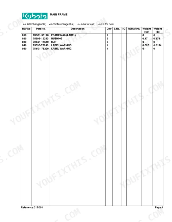
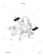
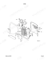
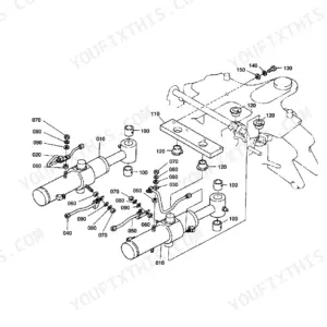
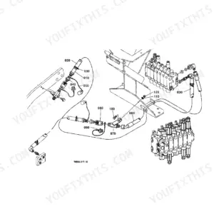
This is the Kubota parts catalog for the BH75 backhoe attachment, a 63-page PDF you download and keep. It breaks the backhoe into its assemblies: the main frame, swing frame, boom, dipperstick, bucket link, bucket and stabilizer, plus the control valve, hydraulic hoses and every cylinder, each shown as an exploded diagram with Kubota part numbers.
Use it to identify the exact part before you order. Match a worn pin, bushing, seal, cylinder or valve component to its number, and use the serial-number columns to confirm the right version for your machine.
The catalog details the control valve and its component parts, the swing, boom, dipper, bucket and stabilizer cylinders, the full set of hydraulic hoses, and three tractor mount kits, making it the reference for any BH75 repair or parts lookup.
Complete the set for your BH75
- Operator Manual: Kubota BH75 Backhoe Operator Manual
What's Inside This Kubota BH75 Parts Manual
| System | Pages | Key Topics |
|---|---|---|
| Hydraulics & 3-Point Hitch | Swing Cylinder, Control Valve, Hydraulic Hose, Cylinder | |
| Loader, Backhoe & Attachments | Swing Frame, Boom, Dipperstick, Bucket Link, Bucket, Stabilizer Arm | |
| Body & Operator Station | Main Frame, Seat | |
| Decals & Accessories | Label | |
| Other Components | Control Lever 1, Control Lever 2, Mount Kit |
Every system also includes interchangeability key.
Kubota BH75 Common Problems This Manual Covers
Weak hydraulics or leak-down after use
Functions that are slow, weak, or drift down after use often point to a leak, contamination in the spool valve, or a pump bypassing. The control valve section maps the valve for diagnosis and reseal.
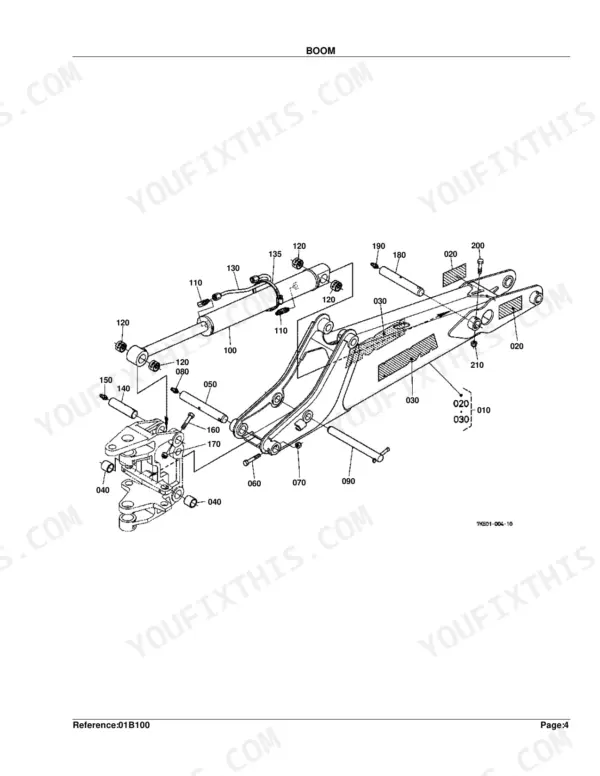
Manual Section: Control Valve p. 20Boom cylinder sticks or will not hold
A cylinder that sticks or fails to hold position usually needs new seals, or the valve is contaminated. The boom cylinder component-parts diagram identifies the seal kit and internal parts.
Manual Section: Cylinder(Boom) [Component Parts] p. 37Sloppy, squeaky controls
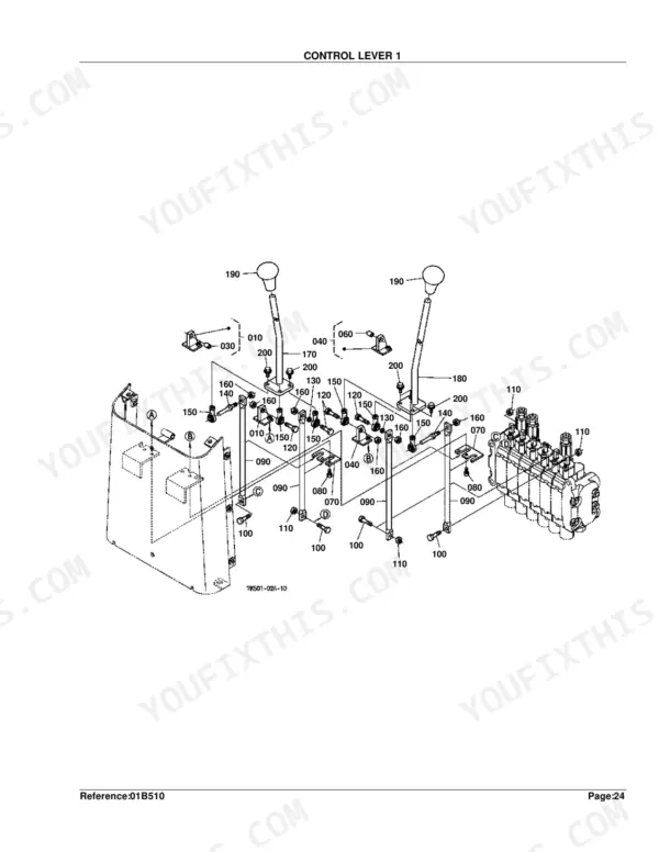
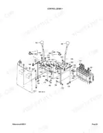
Control linkages develop play and squeaks over time and need tightening and lubrication. This section lists the control-lever parts so you can renew worn pivots and pins.
Manual Section: Control Lever 1 p. 51Hydraulic leak at hoses and fittings
Leaking hoses and fittings are a common cause of weak operation and pressure loss. The intake hose section lists each line and fitting for an exact replacement.
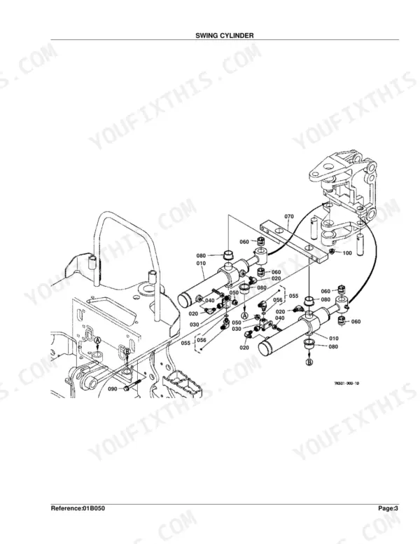
Manual Section: Hydraulic Hose(Intake) p. 25Swing function weak or leaking
The swing cylinder takes heavy loads and can lose power or seep oil. The swing cylinder diagram identifies the adapter, seals and cylinder parts by Kubota number.
Manual Section: Swing Cylinder p. 8Wear after several hundred hours
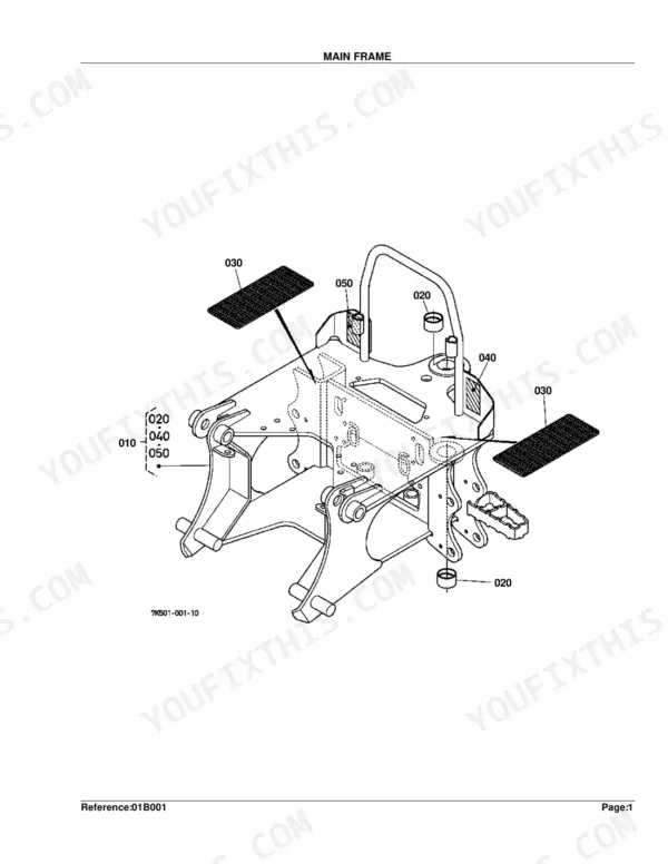
Performance drops as pins, bushings and seals wear from normal service. Use the mount kit and frame diagrams to identify the hardware that keeps the backhoe tight to the tractor.
Manual Section: Mount Kit(D21) p. 57Frequently Asked Questions
What is the Kubota BH75 and does this catalog fit it?
The BH75 is a Kubota backhoe attachment that mounts to compact tractors. This catalog covers the BH75 backhoe, its frame, cylinders, control valve, hoses and mount kits by Kubota part number.
Which tractor mount kits are covered?
The catalog includes three mount kits, listed as Mount Kit (D21), Mount Kit (E27) and Mount Kit (D20), with the hardware needed to fit the backhoe to the tractor. p. 57
Does it detail the hydraulic cylinders?
Yes. The swing, boom, dipper, bucket and stabilizer cylinders each have a component-parts diagram, so you can order seals and internal parts for a rebuild. p. 37
What do I get after purchasing this Kubota BH75 manual?
Instant PDF download. The full 63-page searchable Parts Catalog lands in your account the moment payment clears, ready on a laptop, tablet, or phone in the shop.
Is this Kubota BH75 Parts Catalog printable?
Yes. Print the pages or sections you need for your own shop use. Any standard printer works.
Are hydraulic system diagrams in this Kubota BH75 Parts Catalog?
It includes exploded parts diagrams and part numbers for hydraulic system components, including the boom cylinder seal kit (Part No. 7K501-22300). For wiring or circuit drawings, a separate service manual would be needed — this parts catalog covers assembly identification and ordering information only.





Reviews
There are no reviews yet.