


Part of the Kubota Parts Manuals.
This is the factory parts catalog for the Kubota L2800DT/HST compact tractor, covering both the gear-drive DT and the hydrostatic HST versions. Across 427 pages it lays out every assembly as an exploded diagram paired with a parts table, so each component is matched to its Kubota part number, quantity, and serial-number range.Coverage runs the full machine: engine internals, fuel and cooling systems, the electrical starting and charging circuits, clutch and transmission, hydraulics, steering, front and rear axles, and the 3-point hitch. Use it to identify the exact part before you order, confirm interchangeability between old and new versions, and see which parts differ between the DT and HST builds. Delivered as an instant PDF download with a text layer for searching part numbers, and printable so you can keep it at the bench while you work.
What's Inside This Kubota L2800DT/HST Parts Manual
| System | Pages | Key Topics |
|---|---|---|
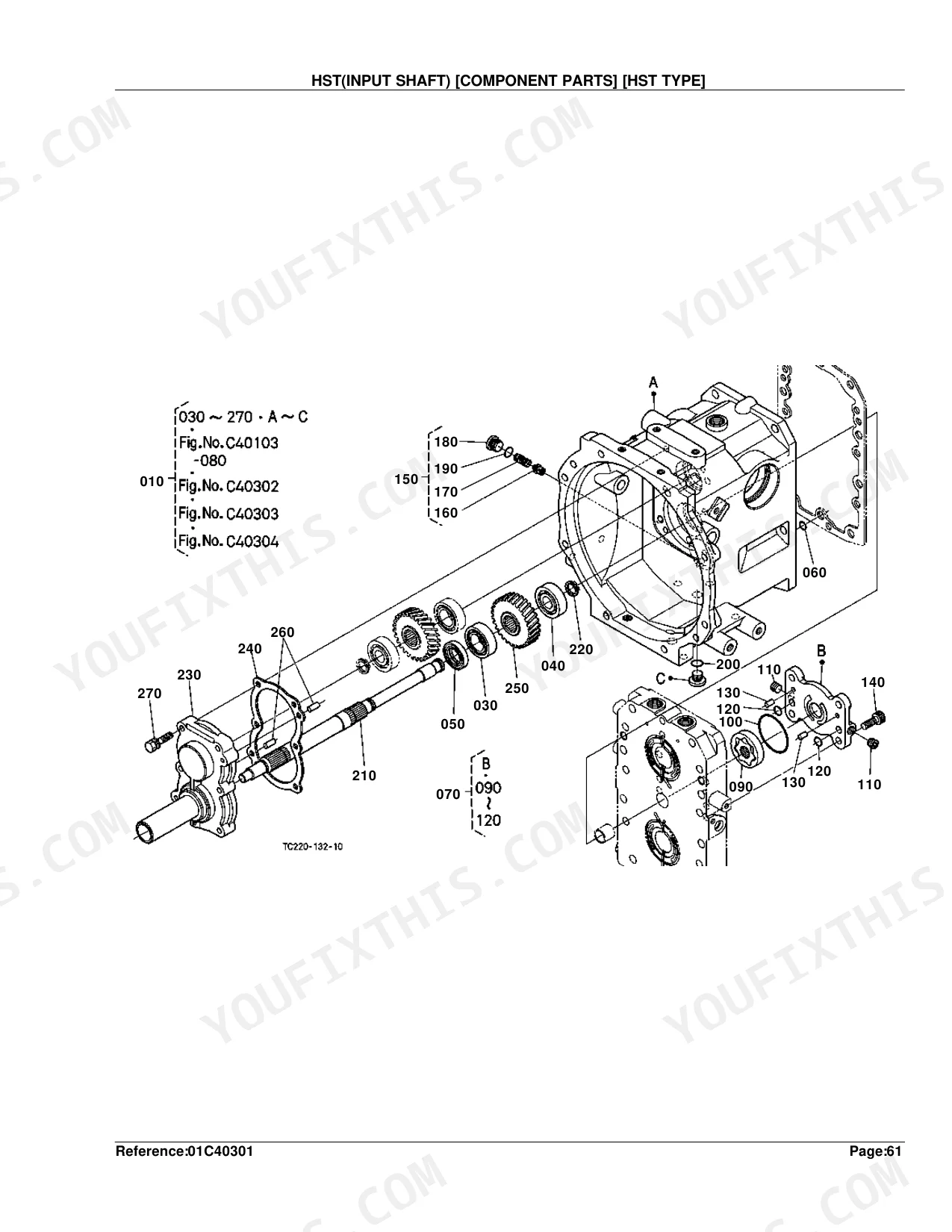
| Clutch & Transmission | Clutch, Clutch Lever, Clutch Pedal, Clutch Housing, HST, Transmission Case, Main Shaft, Countershaft, Reverse Shaft, Range Gear Shaft, PTO Countershaft, Main Gear Shift Fork, Range Gear Shift Fork, PTO Gear Shift Fork, Differential Lock Shift Fork, Main Gear Shift Lever | |
| Fuel System | Fuel Camshaft, Engine Stop Lever, Injection Pump, Governor, Speed Control Plate, Nozzle Holder and Glow Plug, Nozzle Holder, Air Cleaner, Accelerator Lever, Accelerator Linkage, Fuel Tank, Fuel Pipe and Fuel Filter, Fuel Filter, Speed Control Pedal | |
| Cooling System | Water Flange and Thermostat, Water Pump, Fan, Water Pipe, Radiator, Reserve Tank, Oil Cooler | |
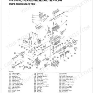
| Engine | Crankcase, Oil Pan, Cylinder Head, Gear Case, Head Cover, Main Bearing Case, Camshaft and Idle Gear Shaft, Piston and Crankshaft, Flywheel, Valve and Rocker Arm, Inlet Manifold, Exhaust Manifold/Muffler, Upper Gasket Kit, Lower Gasket Kit | |
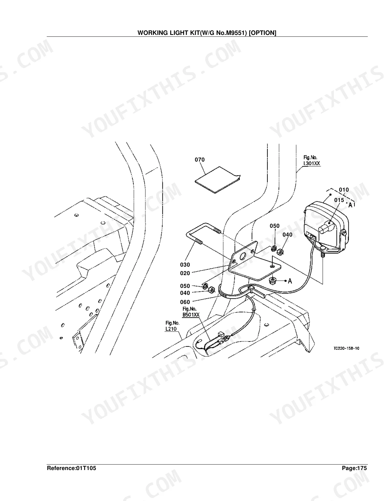
| Electrical System | Alternator, Starter, Battery, Switch/Relay, Switch /Sensor, Switch/Sensor, Panel Board, Head Light, Hazard Light, Rear Lamp, Electrical Wiring, Working Light Kit | |
| PTO | PTO Shaft, PTO Protector | |
| Rear Axle, Differential & Brakes | Spiral Bevel Pinion, Rear Differential, Rear Axle, Brake, Brake Pedal, Parking Brake Lever, Front Axle Case LH, Front Axle Case RH, Differential Gear Shaft, Rear Wheel, Rear Wheel Weight | |
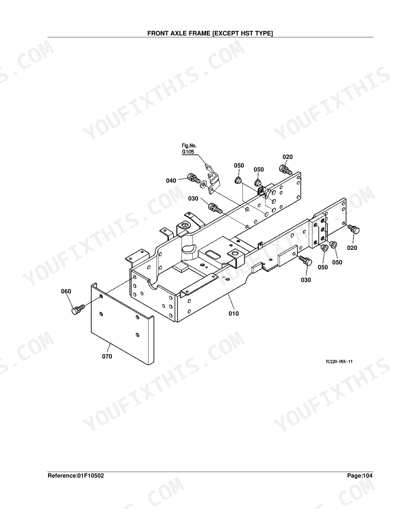
| Front Axle & Steering | Front Wheel Drive Lever, Front Axle Frame, Propeller Shaft, Front Wheel Drive Shaft, Front Differential Case, Front Differential, Front Axle, Steering Handle, Steering, Steering Linkage, Front Wheel | |
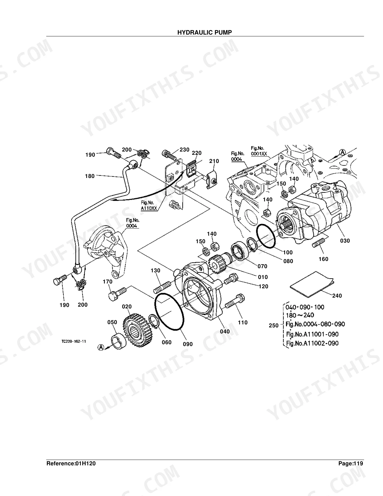
| Hydraulics & 3-Point Hitch | Hydraulic Pump, Hydraulic Oil Line, Hydraulic Outlet Block, Hydraulic Pipe, Hydraulic Cylinder, Cylinder Front Cover, Lift Arm, Feed Back Lever, Control Valve, Position Control Lever, Top Link, 3-Point Linkage 1, 3-Point Linkage 2, Drawbar, Draft Control Lever, Draft Control Valve | |
| Loader, Backhoe & Attachments | Stabilizer | |
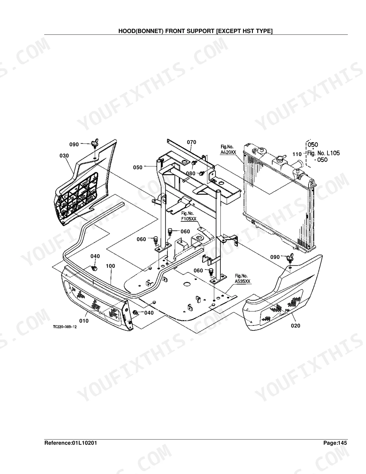
| Body & Operator Station | Cruise Control Cable, Front Grille, Hood Front Support, Hood, Hood Side, Hood Side Cover, Shutter Plate, Hood Rear, Fender, Fender Support, Floor Seat Cover, Seat, Step, ROPS, Smv Emblem | |
| Decals & Accessories | Label 1, Label 2 | |
| Other Components | Cruise Control Lever, Front Bumper, Front Weight |
Every system also includes interchangeability symbols.
Quick Reference Specifications
| Specification | Value | Page |
|---|---|---|
| FUSE | 5A | p. 130 |
| Piston oversize | +0.25mm | p. 27 |
| Crankpin bearing undersize | -0.20mm | p. 27 |
| Injection pump shim thickness | 0.20mm | p. 37 |
| Nozzle holder washer thickness | 0.900mm | p. 46 |
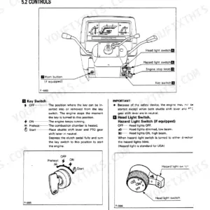
| Headlight bulb power | 25W | p. 97 |
| Fuse rating | 5A | p. 130 |
| Main gear shaft tooth count | 23T | p. 162 |
| Differential gear tooth count | 12T | p. 177 |
| Hydraulic pump gear drive tooth count | 18T | p. 275 |
| Hydraulic outlet block shim thickness | 0.4mm | p. 292 |
Kubota L2800DT/HST Common Problems This Manual Covers
No-start with no crank
A tractor that will not turn over often comes down to a blown fuse, failed relay, or key switch fault. The Switch/Relay figure lists the fuses, relays, and switches with their Kubota part numbers for ordering.
Manual Section: Switch/Relay p. 107Weak charging or dead battery
Slow cranking or a battery that will not hold charge points to the alternator or its internal parts. The Alternator figure breaks out the charging components for replacement.
Manual Section: Alternator p. 94Engine will not shut off cleanly
A fuel shutoff or stop-lever linkage fault can leave the engine running or hard to stop. The Engine Stop Lever figure identifies the linkage parts and their numbers.
Manual Section: Engine Stop Lever p. 33Hard starting diesel
Hard starting or rough running on the diesel often traces to injection pump or nozzle wear. The Injection Pump figure lists the pump and shim parts needed for a rebuild.
Manual Section: Injection Pump p. 35Overheating under load
Overheating usually means a failing water pump, clogged radiator, or worn hoses. The Water Pump figure identifies the pump and gasket parts to replace.
Manual Section: Water Pump p. 50Fuel starvation or clogged filter
Power loss or stalling often traces to a clogged fuel filter. The Fuel Filter [Component Parts] figure lists the filter element and bowl parts.
Manual Section: Fuel Filter [Component Parts] p. 80Frequently Asked Questions
What does this catalog cover?
It is the factory parts catalog for the Kubota L2800DT and L2800HST tractors, covering both the gear-drive and hydrostatic versions. Every assembly is shown as an exploded diagram with a matching part-number table.
Does it include Kubota part numbers?
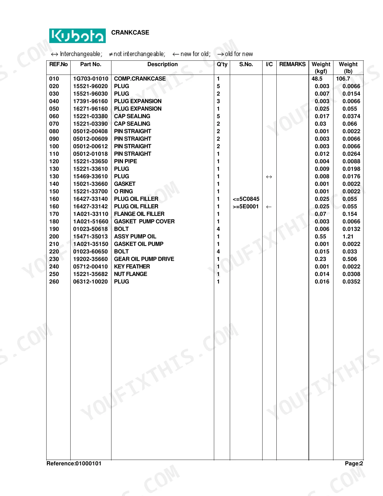
Yes. Each figure is paired with a parts table listing the Kubota part number, description, quantity, and serial-number range. The engine listing begins with the Crankcase figure. p. 8
How do I find the right electrical parts?
The electrical parts are grouped together: the Alternator figure covers charging, the Starter figure covers cranking, and the Switch/Relay figure covers fuses and relays. Match your part on the diagram, then read its number from the table. p. 94
Are the DT and HST parts listed separately?
Yes. Where parts differ, the catalog splits them, such as the Fuel Pipe and Fuel Filter [Hst Type] figure versus the Except HST Type version. Remarks and interchangeability notes flag which part fits your build. p. 77
Is this Kubota L2800DT/HST Parts Catalog a digital download?
A 427-page Parts Catalog in searchable PDF format (5 MB), available the moment you complete checkout. View on computer, tablet, or phone, with no shipping wait.
Is this Kubota L2800DT/HST Parts Catalog printable?
Zero restrictions. The PDF is DRM-free. Print whatever sections you need to take out to the shop. Standard letter or A4 paper works.


Reviews
There are no reviews yet.