
Part of the Kubota Parts Manuals.
This is the Kubota BH65 parts catalog, an illustrated parts breakdown for the BH65 backhoe attachment. Each assembly is shown as an exploded diagram keyed to a list of Kubota part numbers, quantities, and reference numbers.
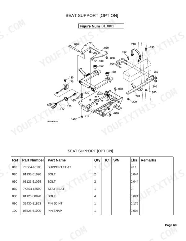
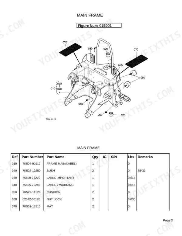
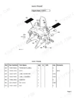
Across 76 pages the catalog covers the main frame and swing frame, the front attachments (swing cylinder, boom, dipperstick, bucket link, bucket, and stabilizer arm), the control valve and its spool sections, the hydraulic hoses and cylinders, the operator's platform, the control levers, labels, and optional equipment such as the mount kit, seat support, and thumb arm kit.
Use it to identify the correct part before you order, confirm quantities, and match components to your machine using the listed serial number ranges and interchangeability notes. It is the reference for rebuilding cylinders or replacing worn pins, bushings, and hoses.
What's Inside This Kubota BH65 Parts Manual
| System | Pages |
|---|---|
| Main Frame | |
| Swing Frame | |
| Front Attachments | |
| Control Valve | |
| Hydraulic System | |
| Hydraulic Cylinder | |
| Operator'S Platform | |
| Control Lever | |
| Labels | |
| Option |
Quick Reference Specifications
| Specification | Value | Page |
|---|---|---|
| BUSH dimension | 35*31 mm | p. 3 |
| FITTING GREASE thread | 1/8-27NPT | p. 5 |
| PIN dimension | 25*107 mm | p. 8 |
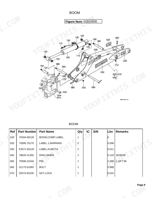
| BOOM RING,INNER dimension | 30/35/30 mm | p. 10 |
| BOOM PIN dimension | 1.18*7.96 inches | p. 10 |
| DIPPERSTICK PIN dimension | 25*137 mm | p. 13 |
| STABILIZER ARM PIN dimension | 25.4*105 mm | p. 18 |
| CYLINDER(SWING) HEAD dimension | 60*30 mm | p. 44 |
| NIPPLE GREASE thread | M8*1.25 | p. 45 |
Kubota BH65 Common Problems This Manual Covers
Weak or slow backhoe operation
After hookup the backhoe can move weakly or slowly when hydraulic oil is low or the circuit is air-bound. The hydraulic system group identifies the intake and function hoses that carry oil through the attachment.
Manual Section: Hydraulic System p. 35Leaking or worn hydraulic cylinders
Boom, dipper, bucket, swing, and stabilizer cylinders lose seal and start weeping with use. The hydraulic cylinder group breaks each cylinder into its component parts so you can order the right seals and pieces.
Manual Section: Hydraulic Cylinder p. 43Worn boom and dipper pins and bushings
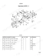
The pins, inner rings, and bushings in the boom and dipperstick linkage wear and develop play over time. The front attachments group lists these parts with their dimensions for replacement.
Manual Section: Front Attachments p. 7Erratic or unresponsive controls
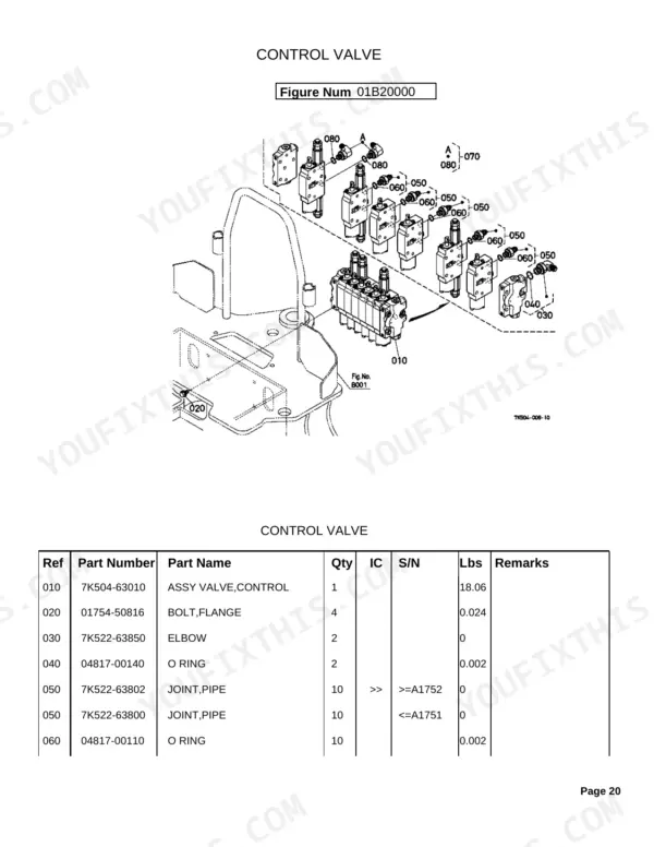
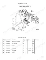
Sticky or erratic function response can come from wear inside the control valve spool sections. The control valve group breaks down each spool section into its component parts.
Manual Section: Control Valve p. 20Loose or worn control levers
Vague or loose control feel often traces to worn parts in the control lever assemblies. The control lever group identifies the lever components you need to restore precise operation.
Manual Section: Control Lever p. 57Difficult mounting or worn mount hardware
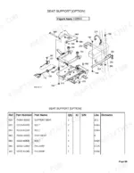
The BH65 can be awkward to attach when the mount kit hardware is worn or the machine is not level. The option group lists the mount kit and its parts for the hookup.
Manual Section: Option p. 65Frequently Asked Questions
What is included in this catalog?
This is a Kubota BH65 parts catalog: exploded diagrams paired with genuine Kubota part numbers, quantities, and reference numbers for every assembly on the backhoe attachment. It is a parts reference, not a repair procedure manual.
Can I order parts using this manual?
Yes. Each diagram lists the factory part number, quantity, and reference number, plus serial number ranges and interchangeability notes, so you can identify and order the correct part.
Does it break down the hydraulic cylinders?
Yes. The hydraulic cylinder group covers the swing, boom, dipper, bucket, and stabilizer cylinders as component parts, so you can order seals and internals by part number. p. 43
Does it show the control valve internals?
Yes. The control valve group includes the swing, boom, stabilizer, dipperstick, and bucket spool sections as component parts, each keyed to Kubota part numbers. p. 20
What format is this manual in?
This is a 76-page searchable PDF ready for immediate download. It works on any device, so you can pull it up on your phone while you are under the hood. No shipping, no waiting.
Can I print specific sections of this Kubota BH65 Parts Catalog?
Yes. Print a chapter or just the pages for the job at hand, for use in your own shop. Any home or office printer works.
Are hydraulic system diagrams in this Kubota BH65 Parts Catalog?
Yes. Exploded views of hydraulic components, hose routing, and cylinder breakdowns are included, showing part numbers for all hydraulic system elements.


Reviews
There are no reviews yet.