


Part of the Kubota Parts Manuals.
This Kubota parts catalog covers the L2350DT tractor and serves as the factory reference for identifying and ordering genuine replacement parts. Its 275 pages organize the machine into exploded diagrams with reference numbers, part numbers, and quantities for each assembly.Coverage runs from the engine (crankcase, flywheel, injection pump, glow plugs) through the fuel and cooling systems, electrical components, clutch, transmission and gear shift assemblies, differentials, axles, brakes, steering, and hydraulics. Every diagram is backed by a parts list, so a worn part can be matched to its exact Kubota number before you order.Built for owners and mechanics repairing an older L2350DT, this PDF makes parts lookup straightforward, whether you are chasing a starting fault, rebuilding a transmission, or sourcing a single fastener.
What's Inside This Kubota L2350DT Parts Manual
| System | Pages | Key Topics |
|---|---|---|
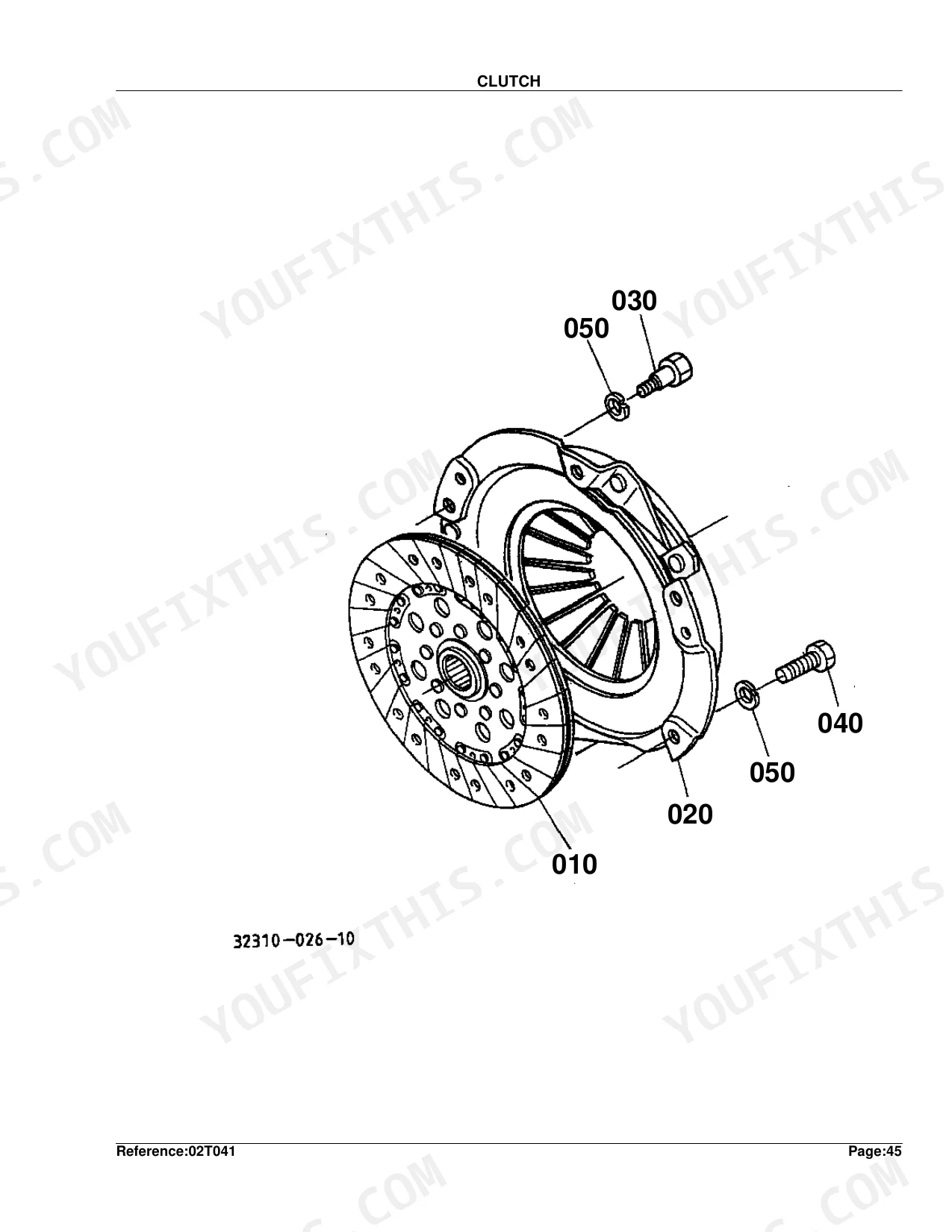
| Clutch & Transmission | Clutch, Clutch Lever, Clutch Pedal, Clutch Housing, Transmission Case, Main Shaft, Countershaft, PTO Countershaft, Reverse Shaft, Main Gear Shift Lever, PTO Gear Shift Lever, Main Gear Shift Fork, PTO Gear Shift Fork, PTO Gear Shift Fork and Lever | |
| Fuel System | Nozzle Holder and Glow Plug, Nozzle Holder, Injection Pump and Fuel Camshaft, Injection Pump, Speed Control Plate, Governor, Air Cleaner, Hand Accelerator Lever, Fuel Tank, Fuel Filter and Fuel Pipe | |
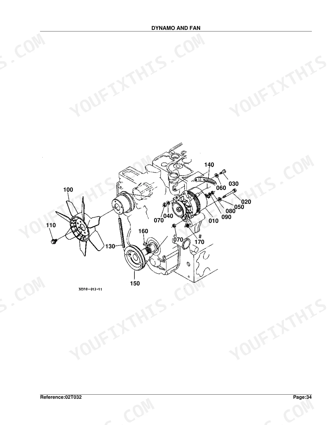
| Cooling System | Water Pump, Water Flange and Thermostat, Water Pipe, Radiator, Dynamo and Fan | |
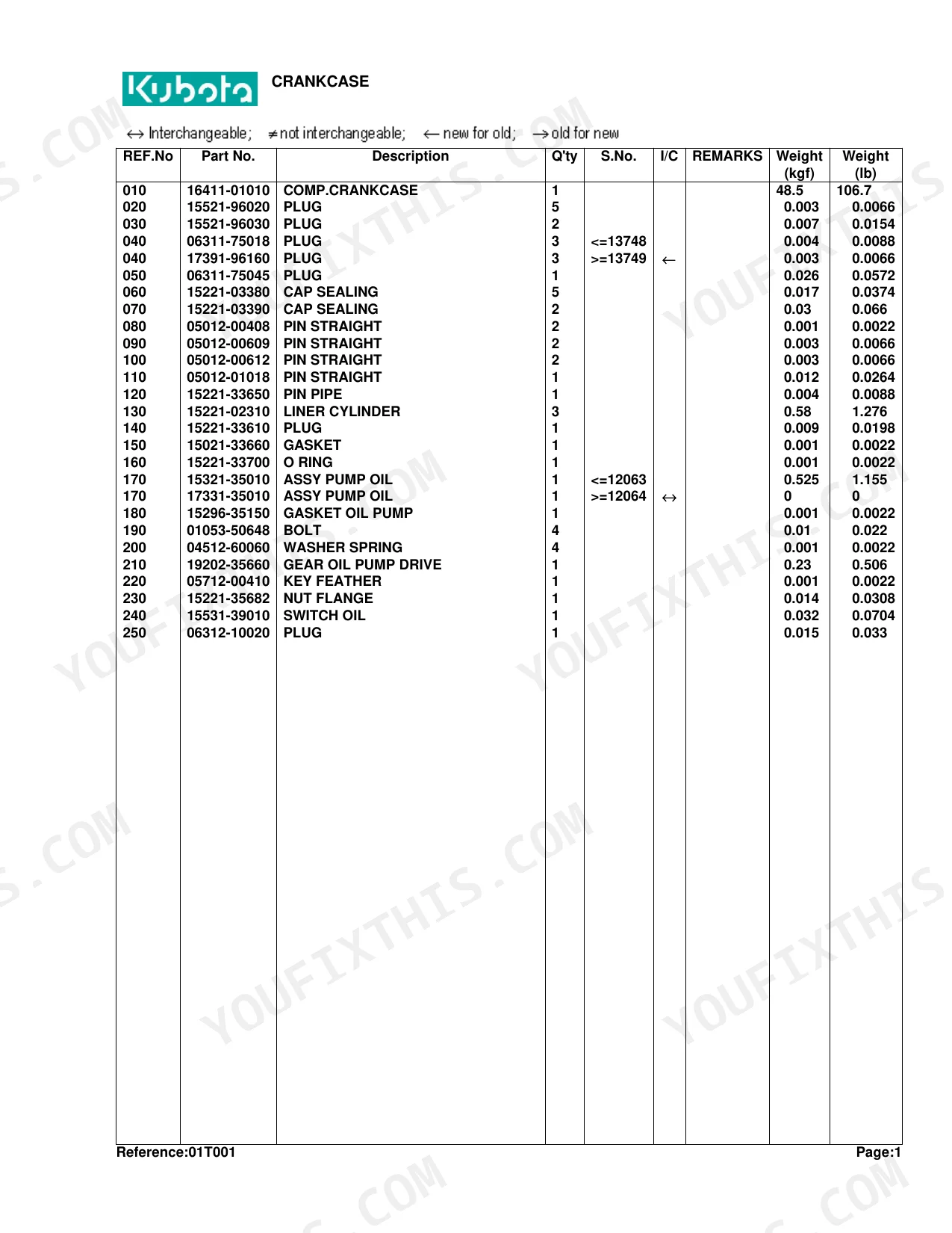
| Engine | Crankcase, Oil Pan, Piston and Crankshaft, Main Bearing Case, Flywheel, Cylinder Head, Valve and Rocker Arm, Cylinder Head Cover, Inlet Manifold, Camshaft, Gear Case, Upper Gasket Kit, Lower Gasket Kit, Exhaust Manifold, Muffler, Under Muffler | |
| Electrical System | Dynamo, Starter, Battery, Switch, Light, Regulator and Meter, Electrical Wiring | |
| PTO | PTO Shaft Protector | |
| Rear Axle, Differential & Brakes | Spiral Bevel Pinion, Rear Differential, Differential Lock Pedal, Rear Axle, Rear Wheel, Brake, Brake Pedal, Parking Brake Lever, Front Axle Case, Differential Gear Shaft | |
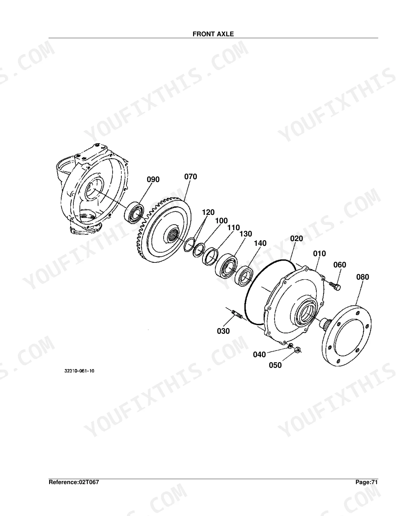
| Front Axle & Steering | Front Axle, Front Differential Case, Front Differential, Propeller Shaft, Front Wheel Drive Case, Front Wheel Drive Lever, Front Wheel, Front Axle Frame, Steering Linkage, Manual Steering and Handle, Power Steering and Handle, Manual Steering, Power Steering | |
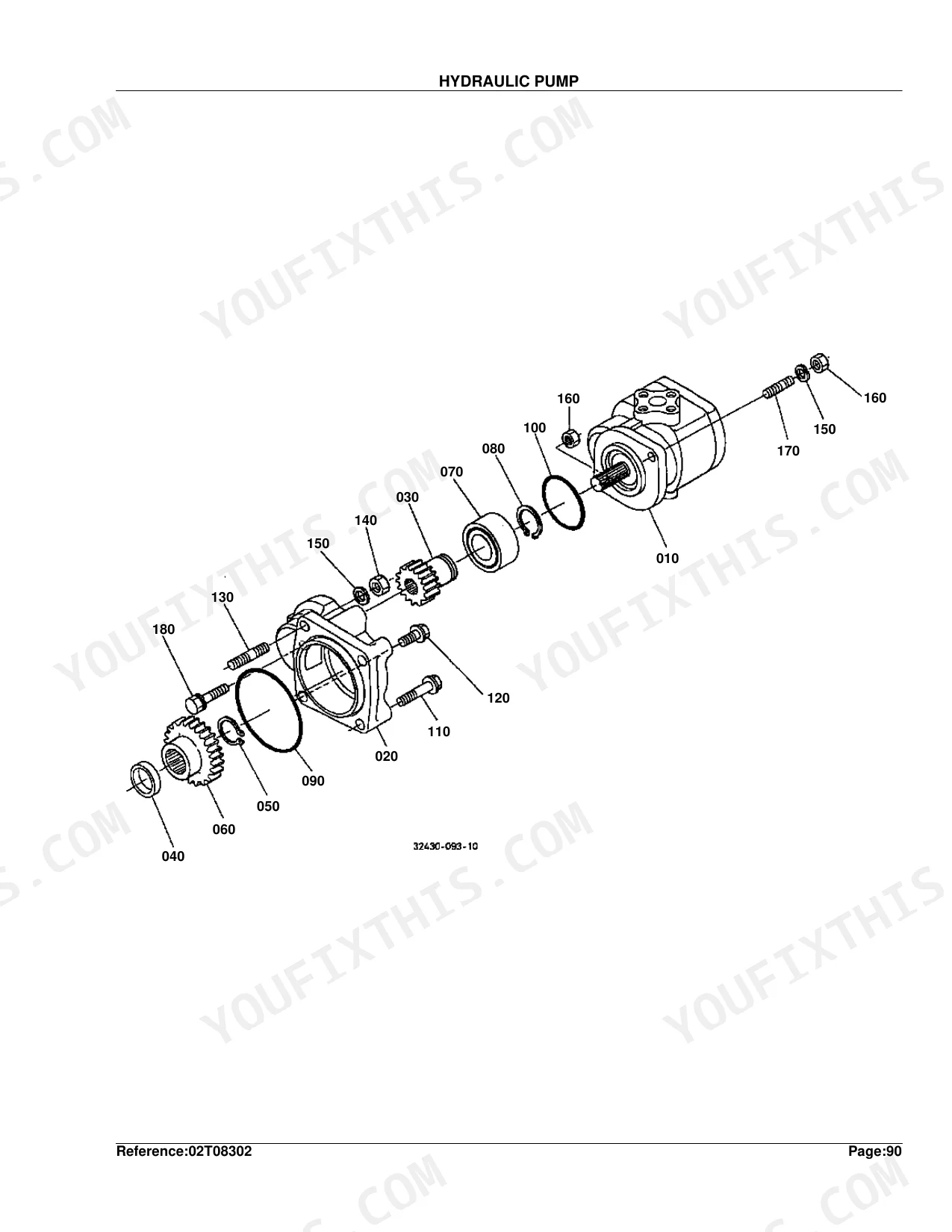
| Hydraulics & 3-Point Hitch | Hydraulic Pump, Flow Priority Valve, Control Valve, Draft Control Valve, Hydraulic Cylunder, Lift Arm, Feed Back Laver, Position Control Lever, 3-Point Linkage 1, 3-Point Linkage 2, Top Link Bracket and Lower Link Holder, Top Link Bracket, Drawbar and Hitch | |
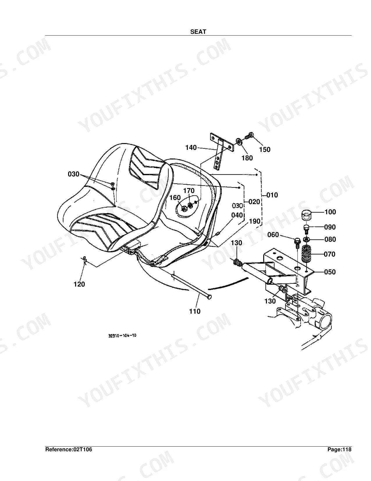
| Body & Operator Station | Shutter, Cylionder Front Cover, Front Grille, Hood, Fender, Seat, Step, Fender Support, ROPS | |
| Decals & Accessories | Label 1, Label 2, Accessories and Service Parts | |
| Other Components | Hudraulic Oil Line |
Every system also includes overview, a parts list, and an exploded view.
Quick Reference Specifications
| Specification | Value | Page |
|---|---|---|
| Gear (REF.No 060) | 32T | p. 115 |
| Gear (REF.No 070) | 41T | p. 115 |
| Piston Size Adjustment (Oversize) | +0.50MM | p. 13 |
| Crankpin Size Adjustment (Undersize) | -0.20MM | p. 13 |
| Nozzle Holder Washer Adjustment Thickness | 1.00MM | p. 27 |
Kubota L2350DT Common Problems This Manual Covers
Abnormal starting or key switch fault
Owners report unusual key and start behavior on the L2350, often tied to the ignition switch. The Switch section shows the correct part numbers to renew the main and combination switches.
Manual Section: Switch p. 89Weak glow-plug preheat
Hard cold starts can follow a failed glow plug or nozzle-holder circuit. The Nozzle Holder and Glow Plug section identifies the plugs and holders needed to restore reliable preheat.
Manual Section: Nozzle Holder and Glow Plug p. 24Tachometer pegs out at high RPM
A tach that reads correctly at idle but pegs at speed usually means a failing gauge or cable. The Regulator and Meter section lists the meter and flexible cable part numbers.
Manual Section: Regulator and Meter p. 95Transmission gear wear
Whine or difficulty selecting gears can trace to worn countershaft gears. The Countershaft section provides the exploded view and gear part numbers for a transmission rebuild.
Manual Section: Countershaft p. 114Clutch wear and hard shifting
A worn clutch disc makes engagement rough and shifting difficult. The Clutch section identifies the disc and related parts so you order the right components before splitting the tractor.
Manual Section: Clutch p. 101No-crank starter fault
Slow or dead cranking often points to the starter or its internal parts. The Starter section and its component parts break the unit down for a targeted repair.
Manual Section: Starter p. 82Fuel starvation from filter or line
A clogged filter or aged fuel line can choke fuel flow and stall the engine. The Fuel Filter and Fuel Pipe section lists the filter and line parts to renew.
Manual Section: Fuel Filter and Fuel Pipe p. 70Frequently Asked Questions
What does this catalog cover?
It is the parts catalog for the Kubota L2350DT tractor, with exploded diagrams and part numbers spanning the engine, driveline, electrical, steering, and hydraulic systems over 275 pages.
How do the part numbers work?
Each diagram uses reference numbers that match a parts list giving the Kubota part number, description, quantity, and serial-number range, so you order the correct part for your tractor.
Can I find transmission gear parts?
Yes. The Countershaft and related transmission sections show the exploded views and gear part numbers, including tooth counts, for a rebuild. p. 114
How quickly can I access this manual after buying?
Instant download. The full 275-page searchable Parts Catalog is yours the moment payment clears, ready to open on a laptop, tablet, or phone right there in the shop.
Are there any print restrictions on this manual?
No — the PDF ships DRM-free, so print whatever sections you want to carry out to the shop. Standard letter or A4 paper both work.


Reviews
There are no reviews yet.