


Part of the Kubota Parts Manuals.
This Kubota parts catalog covers the L2500DT tractor and is the factory reference for identifying and ordering genuine replacement parts. Across 247 pages it breaks the machine into exploded diagrams with reference numbers, part numbers, and quantities for every assembly.Sections cover the engine (crankcase, pistons, injection pump), the fuel and cooling systems, electrical components, the clutch, transmission and gear shift assemblies, front and rear axles, brakes, steering, and hydraulics. Each diagram pairs with a parts list so a worn component can be matched to its exact Kubota part number.For owners and mechanics keeping an L2500DT in service, this PDF removes the guesswork from parts lookup, whether you are tracing a 4WD driveline fault, sorting out an electrical no-start, or renewing major service parts.
What's Inside This Kubota L2500DT Parts Manual
| System | Pages | Key Topics |
|---|---|---|
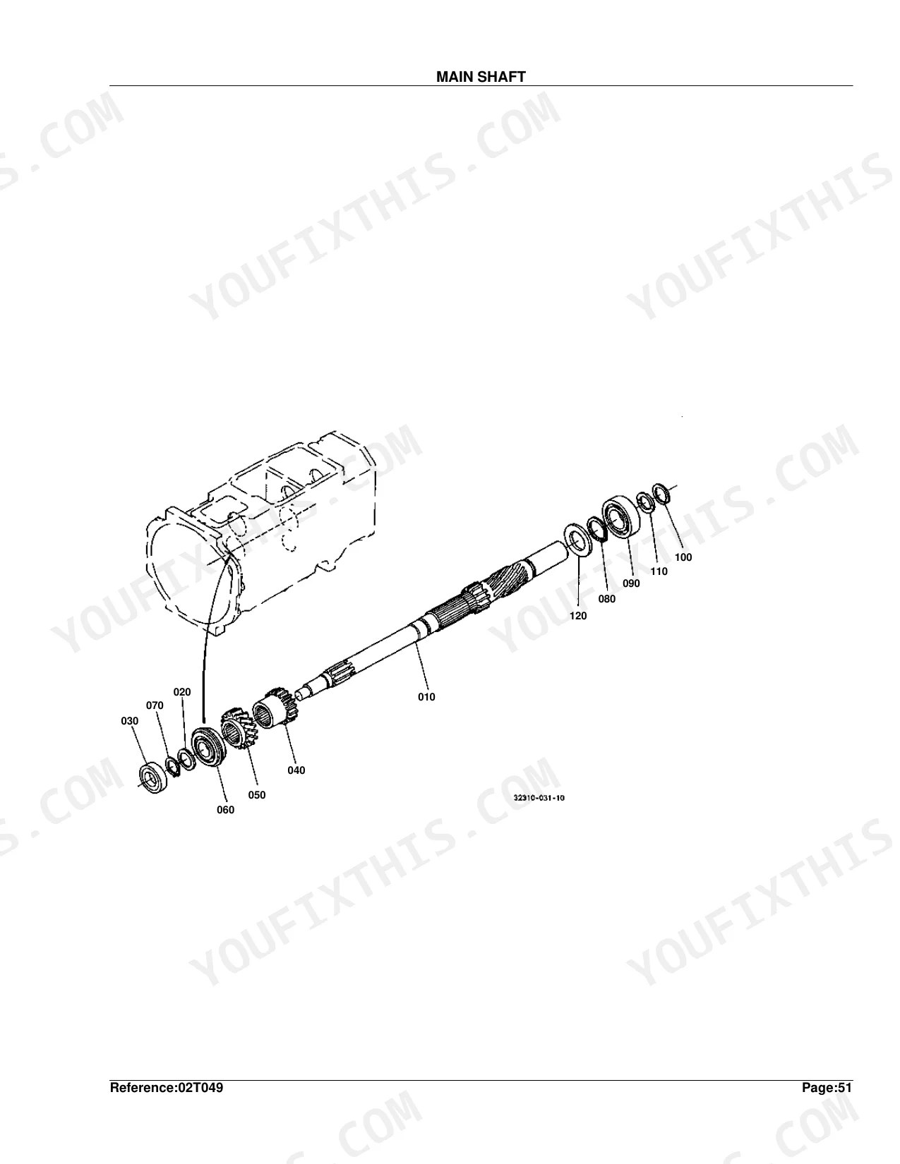
| Clutch & Transmission | Clutch, Clutch Lever, Clutch Pedal, Clutch Housing, Transmission Case, Main Shaft, Countershaft, PTO Countershaft, Reverse Shaft, Main Gear Shift Lever, PTO Gear Shift Lever, Main Gear Shift Fork, PTO Gear Shift Fork, Range Gear Shift Fork and Lever | |
| Fuel System | Nozzle Holder/Glow Plug, Nozzle Holder, Fuel Camshaft, Injection Pump, Engine Stop Lever, Speed Control Plate, Governor, Air Cleaner, Hand Accelerator Lever, Fuel Tank, Fuel Filter/Fuel Pipe | |
| Cooling System | Water Pump, Water Flange and Thermostat, Fan, Water Pipe, Radiator | |
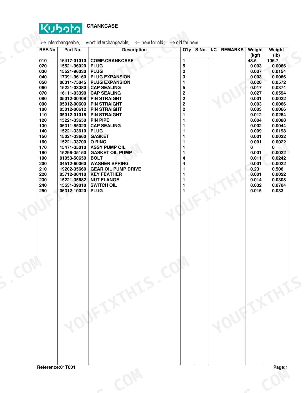
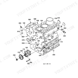
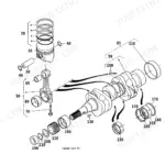
| Engine | Crankcase, Oil Pan, Piston/Crankshaft, Main Bearing Case, Flywheel, Cylinder Head, Valve and Rocker Arm, Cylinder Head Cover, Inlet Manifold, Exhaust Manifold, Camshaft, Gear Case, Upper Gasket Kit, Lower Gasket Kit, Muffler, Under Muffler | |
| Electrical System | Alternator, Starter, Battery, Switch, Light, Meter, Electrical Wiring | |
| PTO | PTO Shaft Protector | |
| Rear Axle, Differential & Brakes | Spiral Bevel Pinion, Rear Differential, Differential Lock Pedal, Rear Axle, Rear Wheel, Brake, Brake Pedal, Parking Brake Lever, Front Axle Case, Differential Gear Shaft | |
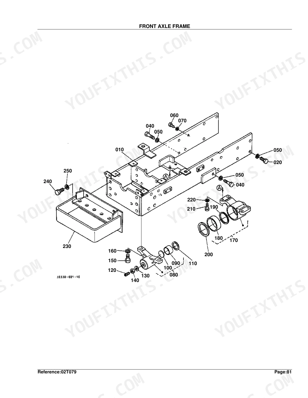
| Front Axle & Steering | Front Axle, Front Differential Case, Front Differential, Propeller Shaft, Front Wheel Drive Lever, Front Wheel, Front Axle Frame, Steering Linkage, Manual Steering and Handle, Power Steering and Handle, Manual Steering, Power Steering | |
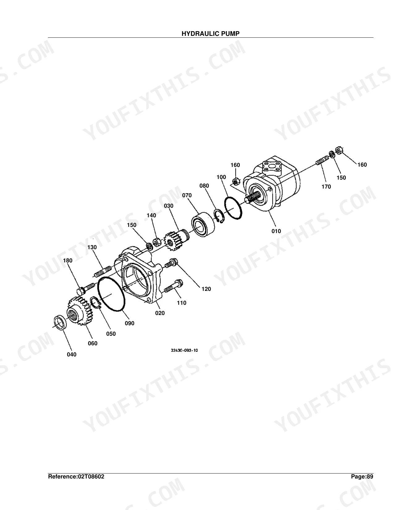
| Hydraulics & 3-Point Hitch | Hydraulic Pump, Hydraulic Oil Line, Flow Priority Valve, Control Valve, Draft Control Valve, Hydraulic Cylinder, Cylinder Front Cover, Lift Arm, Feed Back Lever, Position Control Lever, 3-Point Linkage 1, 3-Point Linkage 2, Top Link Bracket/Lower Link Holder, Top Link Bracket, Drawbar/Hitch | |
| Body & Operator Station | Shutter, Front Grille, Hood, Rear Hood, Fender, Fender Support, Seat, Step, ROPS | |
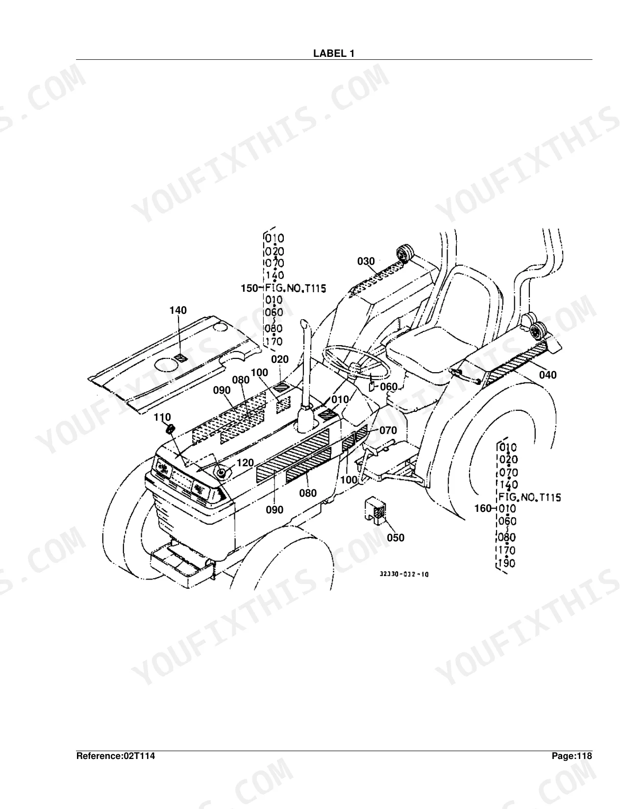
| Decals & Accessories | Label 1, Label 2, Accessories and Service Parts | |
| Other Components | Stop Rod, Front Sheel Drive Case |
Every system also includes interchangeability symbols.
Quick Reference Specifications
| Specification | Value | Page |
|---|---|---|
| Fuse | 10A | p. 95 |
| Link Fusible | 40A | p. 95 |
| Differential Gear Shaft Shim | 0.40MM | p. 150 |
| Control Valve (Position Control) Shim | 0.40MM | p. 196 |
Kubota L2500DT Common Problems This Manual Covers
No pull in 4WD
Loss of front-wheel drive commonly comes from a stripped front coupler on the propeller shaft. The Propeller Shaft section identifies the shaft and coupling parts so you can restore torque to the front axle.
Manual Section: Propeller Shaft p. 155No-start from blown fuse
A blown fuse or fusible link often sits behind a dead electrical system. The Electrical Wiring section lists the fuses and fusible link along with their ratings.
Manual Section: Electrical Wiring p. 94Faulty key switch
Intermittent or no start after key-on can trace to the ignition switch. The Switch section shows the correct part number for the main switch and related contacts.
Manual Section: Switch p. 88Weak or no charging
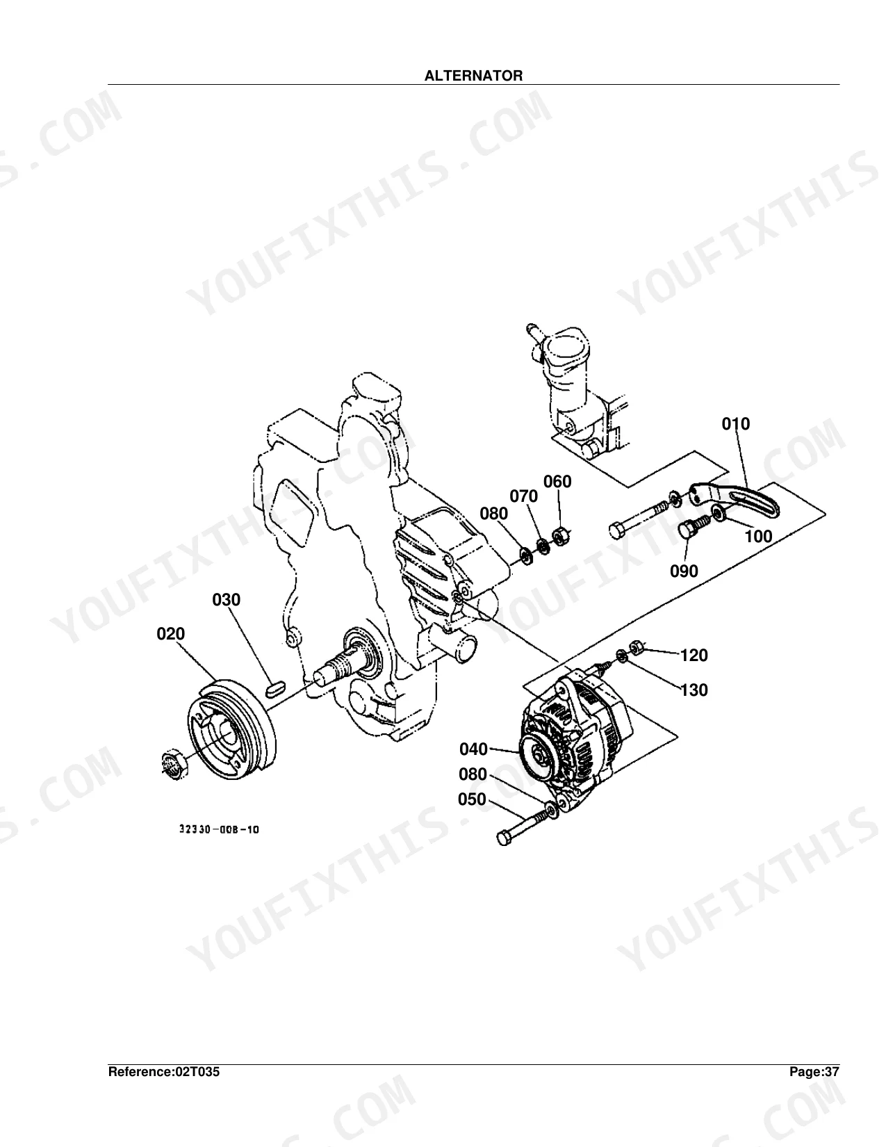
A discharged battery while running usually means a failed alternator. The Alternator section and its component parts identify the unit and internal parts for a repair or swap.
Manual Section: Alternator p. 78No-crank starter fault
Slow or silent cranking points to the starter or solenoid. The Starter section and its component parts break the assembly down so you can replace only the failed part.
Manual Section: Starter p. 82Overheating from radiator issues
Rising temperature can follow a clogged or damaged radiator. The Radiator section shows the core, cap, and mounting parts needed to renew the cooling stack.
Manual Section: Radiator p. 72Clutch wear and squeal
A worn or dry clutch causes slipping and noise on engagement. The Clutch section provides the diagram and part numbers for the disc and related components.
Manual Section: Clutch p. 96Frequently Asked Questions
What does this catalog cover?
It is the parts catalog for the Kubota L2500DT tractor, with exploded diagrams and part numbers for the engine, driveline, electrical, steering, and hydraulic systems across 247 pages.
Does it show 4WD driveline parts?
Yes. The Propeller Shaft and front axle sections show the exploded views and part numbers for the front driveline, including the coupler that commonly fails in 4WD. p. 155
Can I look up electrical parts?
Yes. The Electrical Wiring section lists fuses and the fusible link with their ratings, and the Switch, Alternator, and Starter sections cover the rest of the starting and charging circuit. p. 94
Is this Kubota L2500DT Parts Catalog a digital download?
Instant PDF download (4 MB). You get the full 247-page searchable Parts Catalog immediately after payment. Open it on your laptop, tablet, or phone right in the shop.
Is this Kubota L2500DT Parts Catalog printable?
Yes. The PDF has no DRM restrictions, so print any page or section you need for your shop. Works with any standard printer.


Reviews
There are no reviews yet.